Quantum PX500 Series, User Manual
The Quantum PX500 Series, a cutting-edge storage solution, offers unrivaled performance and reliability. Ensure a seamless installation process with our comprehensive Installation Instructions Manual. This essential manual can be easily downloaded for free from our website, allowing you to optimize your experience with Quantum PX500 Series effortlessly.
Share
Download


Reviews:
No comments
Related manuals for PX500 Series
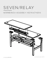
SEVEN
Brand: WATSON Pages: 12

ES.2 - Barracuda Enterprise 750GB SATA/300 7200RPM 32MB Hard Drive
Brand: Seagate Pages: 2

SpycerBox Cell
Brand: R&S Pages: 78

DS-HSZ22-AA
Brand: DEC Pages: 94

03BUT0606-V1
Brand: Mercia Garden Products Pages: 9

N7800
Brand: IBM Pages: 182

400A-72-124
Brand: morse Pages: 5

400A-60-124
Brand: morse Pages: 6

Portable Hard Drive Combo USB
Brand: Verbatim Pages: 31

Hybrid 2
Brand: ClearStream Pages: 2

M300 Pico
Brand: Canyon Hydro Pages: 52

KRB04
Brand: Kimberley Pages: 2

TVVR70020
Brand: Abus Pages: 44

Porsche Design P 9231
Brand: LaCie Pages: 1

WD10000H1CS-00 - Home Edition
Brand: Western Digital Pages: 2

SD25B-100
Brand: SanDisk Pages: 69

SDP3B
Brand: SanDisk Pages: 111

JBOD2312S3SP
Brand: Intel Pages: 47


