PRONAR T679/5 Operator'S Manual Download Page 93

SECTION 5 

PRONAR T679/5 

5.21 

5.3.3  INSPECTION OF THE SYSTEM 


INSPECTION 


  Each time during tightness inspection. 

 
During  tightness  inspection  attention  should additionally  be  given  to  technical  condition and 

degree of cleanness of the system components. Contact of pneumatic conduit seals etc. with 

oil,  grease,  petrol  etc.  may  cause  damage  and  accelerate  the  ageing  process.  Bent, 

permanently deformed, cut or worn conduits should be replaced. 

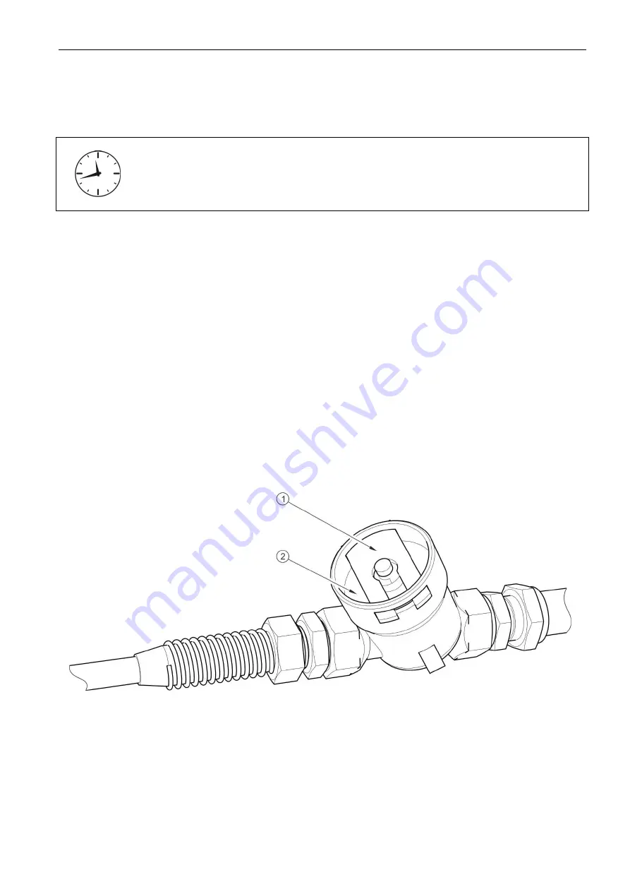
5.4  CLEANING THE AIR FILTERS 

Depending on trailer working conditions, but not less than once in three months, take out and 

clean air filter elements, which are located in pneumatic system connection conduits. Inserts 

are  used  many  times  and  are  not  subject  to  changing  unless  they  are  mechanically 

damaged. 


FIGURE 5.12  Air filter 

(1) securing slide lock, (2) air filter cover 

Required maintenance activities 

  Reduce pressure in supply conduit. 

Summary of Contents for T679/5

Page 1: ... 48 085 681 63 29 48 085 681 64 29 48 085 681 63 81 48 085 681 63 82 fax 48 085 681 63 83 48 085 682 71 10 www pronar pl OPERATOR S MANUAL AGRICULTURAL TRAILER PRONAR T679 5 TRANSLATION OF THE ORIGINAL COPY OF THE MANUAL EDITION 2A 04 2017 PUBLICATION NO 537N 00000000 05 UM ...

Page 2: ......

Page 3: ...ation Before using the machine the user must carefully read this Operator s Manual and observe all recommendations This guarantees safe operation and ensures failure free work of the machine The machine is designed to meet obligatory standards documents and legal regulations currently in force The manual describes the basic safety rules and operation of agricultural trailer Pronar T679 5 If the in...

Page 4: ...arly important information and instructions the observance of which is essential are distinguished in the text by the sign and also preceded by the word ATTENTION Failure to observe the instructions may lead to damage to the machine as a result of improper operation adjustment or use In order to focus the user s attention on the need to perform maintenance the relevant section of the Operator s Ma...

Page 5: ...rward travel Right side side to the right hand of the operator facing in the direction of machine s forward travel REQUIRED MAINTENANCE ACTIVITIES Maintenance actions described in the manual are marked with the sign Result of maintenance adjustment actions or comments concerning the performance of actions are marked with the sign ...

Page 6: ......

Page 7: ...F WARRANTY 1 10 1 5 TRANSPORT 1 11 1 5 1 TRANSPORT ON VEHICLE 1 11 1 5 2 INDEPENDENT TRANSPORT BY THE USER 1 13 1 6 ENVIRONMENTAL HAZARDS 1 14 1 7 WITHDRAWAL FROM USE 1 15 2 SAFETY ADVICE 2 1 2 1 SAFETY INFORMATION 2 2 2 1 1 BASIC SAFETY RULES 2 2 2 1 2 DRIVING ON PUBLIC ROADS 2 6 2 1 3 DESCRIPTION OF RESIDUAL RISK 2 7 2 2 INFORMATION AND WARNING DECALS 2 8 3 DESIGN AND OPERATION 3 1 3 1 TECHNICAL...

Page 8: ...E TRAILER FOR THE FIRST USE TEST RUN OF THE TRAILER 4 3 4 1 4 PREPARING THE TRAILER FOR NORMAL USE 4 4 4 2 HITCHING AND UNHITCHING THE TRAILER 4 5 4 2 1 HITCHING AND UNHITCHING THE SECOND TRAILER 4 7 4 3 LOADING AND SECURING LOAD 4 9 4 3 1 GENERAL INFORMATION ABOUT LOADING 4 9 4 3 2 SECURING LOAD 4 10 4 4 TRANSPORTING LOADS 4 13 4 5 UNLOADING 4 15 4 6 PROPER USE AND MAINTENANCE OF TYRES 4 18 5 MAI...

Page 9: ...S 5 20 5 3 3 INSPECTION OF THE SYSTEM 5 21 5 4 CLEANING THE AIR FILTERS 5 22 5 4 1 DRAINING WATER FROM AIR TANK 5 23 5 4 2 CLEANING DRAIN VALVE 5 23 5 4 3 CLEANING AND MAINTAINING PNEUMATIC CONDUIT CONNECTIONS AND PNEUMATIC SOCKETS 5 24 5 5 HYDRAULIC SYSTEM MAINTENANCE 5 25 5 5 1 PRELIMINARY INFORMATION 5 25 5 5 2 CHECKING HYDRAULIC SYSTEM TIGHTNESS 5 25 5 5 3 CHECKING TECHNICAL CONDITION OF HYDRA...

Page 10: ...5 10 ADJUSTMENT OF DRAWBAR POSITION 5 35 5 11 ADJUSTMENT OF TAILGATE POSITION 5 37 5 12 TROUBLESHOOTING 5 39 5 12 1 TROUBLESHOOTING 5 39 ...

Page 11: ...SECTION 1 BASIC INFORMATION ...

Page 12: ... is marked with the data plate 1 and vehicle identification number VIN 2 The serial number and data plate are located on the right side of the frame front beam figure 1 1 When buying the agricultural trailer check that the serial numbers on the machine agree with the number written in the WARRANTY BOOK and in the sales documents The meanings of the individual fields found on the data plate are pre...

Page 13: ...hitching system loading J Permissible front axle load K Permissible rear axle load 1 1 2 AXLE IDENTIFICATION The serial number of the axle shaft and its type are stamped onto the data plate 2 secured to the axle shaft beam 1 figure 1 2 TIP In the event of ordering a replacement part or in the case of the appearance of problems it is often essential to give the serial number of the agricultural tra...

Page 14: ...ER 1 2 PROPER USE The trailer is designed for transporting and unloading harvested crops and agricultural products as well as heavy materials such as debris stones rubble gravel used during construction work earthwork demolition on the farm and on public roads Load box design enables loading and transport of machinery and construction vehicles as well as transport of goods on EUR pallets ...

Page 15: ...d in particular for transporting people and animals for transporting hazardous loads or loads which are not properly secured against shifting or falling out for transporting loads which are unevenly distributed and or which overload axles and suspension elements Do NOT overload the trailer in excess of its load carrying capacity for transporting any materials other than those stipulated in the man...

Page 16: ...nd transport regulations in force in a given country in which the machine is used carefully read the Operator s Manual and comply with its recommendations only hitch the trailer to an agricultural tractor which fulfils all the requirements made by the trailer s Manufacturer The machine may only be used by persons who are familiar with the contents of this publication and with the contents of the a...

Page 17: ...c system Hydraulic oil Maximum system pressure Oil demand bar l L HL 32 Lotos 1 200 17 Electrical system Electrical system voltage Connection socket V 12 7 pole socket compliant with ISO 1724 Tractor hitches Type of hitch upper or lower transport hitch Other requirements Min tractor power Minimum vertical load capacity of hitch hp kW kg 62 6 46 2 000 1 use of other oil is permitted on condition th...

Page 18: ...7421 1 according to A DIN 74 294 according to ISO 1728 5 8 6 5 6 5 150 Hydraulic tipper system Hydraulic oil Maximum system pressure bar L HL 32 Lotos 1 200 20 Electrical system Electrical system voltage Connection socket V 12 7 pole socket compliant with ISO 1724 Trailer s drawbar Diameter of drawbar eye mm 40 1 use of other oil is permitted on condition that it may be mixed with the oil in the t...

Page 19: ...s Transport lugs for securing load Rear hitch Double line pneumatic braking system Hydraulic brake system Hydraulic tipper system Hydraulic hinged tailgate Hinged opening tailgate Parking brake Lighting system LED 12V Lights support beams with rear lamp shields Slow moving vehicle warning sign Load box service support Mechanical telescopic drawbar support Load box ladder Front canopy of load box W...

Page 20: ... when it is used according to its intended purpose as described in the OPERATOR S MANUAL The repair period is specified in the WARRANTY BOOK The warranty does not cover those parts and sub assemblies of the machine which are subject to wear in normal usage conditions regardless of the warranty period Consumables include the following parts sub assemblies drawbar hitching eye pneumatic system conne...

Page 21: ...rbidden In particular do NOT weld drill holes in cut or heat the main structural elements of the machine which have a direct impact on the machine operation safety 1 5 TRANSPORT The machine is prepared for sale completely assembled and does not require packing Packing is only required for the machine s technical documentation and any extra equipment The agricultural trailer is delivered to the use...

Page 22: ...lements Chocks wooden blocks or other objects without sharp edges should be placed under the wheels of the trailer to prevent it from rolling Wheel blocks must be nailed to the vehicle load platform planks or secured in another manner preventing their movement FIGURE 1 3 Transport lugs 1 transport lug 2 lower longitudinal frame Use certified and technically reliable securing measures Worn straps c...

Page 23: ...th the transport safety requirements and the regulations Driver of the vehicle should be particularly careful during travel Centre of gravity of the vehicle transporting the machine is shifted upwards which poses a threat to stability of the vehicle and transported machine Use only certified and technically reliable securing measures Carefully read the information contained in the Operator s Manua...

Page 24: ...food packaging for this purpose While carrying out maintenance and repair work which involves the risk of an oil leak this work should take place on an oil resistant floor or surface In the event of oil leaking into the environment first of all contain the source of the leak and then collect the leaked oil using available means Remaining oil should be collected using sorbents or by mixing the oil ...

Page 25: ...ing of machines withdrawn from use Before proceeding to dismantle equipment oil shall be completely removed from hydraulic system Worn out or damaged parts that cannot be reclaimed should be taken to a collection point for recyclable raw materials Hydraulic oil should be taken to the appropriate facility dealing with the re use of this type of waste DANGER During dismantling use the appropriate to...

Page 26: ...PRONAR T679 5 SECTION 1 1 16 ...

Page 27: ...SECTION 2 SAFETY ADVICE ...

Page 28: ...ng this machine should be the application of safety rules and sensible behaviour The trailer must never be used by persons who are not authorised to drive agricultural tractors including children and people under the influence of alcohol or other drugs Non compliance with the safety rules of this Operator s Manual can be dangerous to the health and life of the operator and others The trailer must ...

Page 29: ...ng of the load and danger while working or driving Before each use of the trailer check the technical condition of the trailer and tractor hitching system and connection elements of the braking system and electrical system Exercise caution when connecting and disconnecting machine from the tractor Do NOT couple a second trailer if it does not fulfil the requirements specified by the Manufacturer l...

Page 30: ...essure In the event of injuries being caused by pressurised hydraulic oil contact a doctor immediately Hydraulic oil may find its way under the skin and cause infections Use the hydraulic oil recommended by the Manufacturer Never mix two types of oil After changing the hydraulic oil the used oil should be properly disposed of When working on the tyres chocks or other objects without sharp edges sh...

Page 31: ...rinciples of workplace health and safety In the event of injury the wound must be immediately cleaned and disinfected In the event of more serious injuries seek a doctor s advice Repair maintenance and cleaning work should be carried out with the tractor engine turned off and the ignition key removed Regularly check the condition of the bolt and nut connections Before welding or electrical work th...

Page 32: ...ated with lubrication remove excess oil or grease Use appropriate tools close fitting protective clothing and gloves when operating maintaining or cleaning the machine 2 1 2 DRIVING ON PUBLIC ROADS FIGURE 2 1 Mounting place for the slow moving vehicle warning sign 1 slow moving vehicle warning sign Comply with the road traffic regulations ...

Page 33: ...ler shall be marked with a slow moving vehicle warning sign attached to the tailgate 2 1 3 DESCRIPTION OF RESIDUAL RISK Pronar Sp z o o in Narew has made every effort to eliminate the risk of accidents There is however a certain residual risk which could lead to an accident and this is connected mainly with the actions described below using trailer for purposes other than those described in the Op...

Page 34: ...use the user of the machine is obliged to take care that notices and warning and information symbols located on the trailer are clear and legible In the event of their destruction they must be replaced with new ones Information and warning decals may be purchased directly from the Manufacturer or your PRONAR dealer Part numbers of information decals are given under pictogram description in table 2...

Page 35: ...ance from electric power lines during unloading 58N 0000020 4 Regularly check if the nuts and bolts fixing the wheels and other components are properly tightened 104N 00000006 5 Grease the machine according to the recommendations in the OPERATOR S MANUAL 104N 00000004 6 Danger of crushing Do NOT perform any maintenance or repairs on the load box that is loaded raised or not supported 58N 0000012 ...

Page 36: ...PRONAR T679 5 SECTION 2 2 10 ITEM SYMBOL MEANING 7 Danger of crushing Maintain a safe distance during opening and closing the tailgate 96N 00000006 8 Machine type 537N 00000006 ...

Page 37: ...SECTION 2 PRONAR T679 5 2 11 FIGURE 2 2 Locations of information and warning decals ...

Page 38: ...PRONAR T679 5 SECTION 2 2 12 ...

Page 39: ...SECTION 3 DESIGN AND OPERATION ...

Page 40: ...ecification Maximum carrying capacity Maximum gross weight Tare weight Load surface kg kg kg m2 8 100 10 350 2 250 9 7 Other information Wheel track Maximum drawbar load Cargo capacity Height of platform from the ground Load box tipping angle to the rear Electrical system voltage Hydraulic oil demand Hydraulic system pressure Tractor power demand Maximum design speed Noise emission level mm kg m3 ...

Page 41: ...s of axle 8 that is bolted to lower frame 1 The axle is made from a square bar ended with pins on which the axle hubs are mounted with the use of cone bearings The wheels are single and equipped with shoe brakes activated by mechanical cam expanders In the front part of the chassis there is mechanical parking stand 3 which supports the trailer disconnected from the tractor Next to the support cond...

Page 42: ...ailer chassis 1 lower frame 2 drawbar 3 mechanical support 4 wheel chocks 5 tipping cylinder socket 6 load box support 7 lights support beam 8 axle 9 drawbar hitching eye 10 parking brake mechanism 11 rear hitch 12 conduit bracket 13 mudguard ...

Page 43: ...truction It is madeof steel plates and shapes figure 3 2 In the side walls there are four fixing lugs 5 which ensure reliable fixing of loads In the rear part of the load box there is tailgate 2 which is opened and closed using a hydraulic cylinder The tailgate is opened downwards Optionally the trailer can be equipped with hinged opening tailgate 4 with mechanical adjustment of tailgate opening A...

Page 44: ...ent grades of steel in order to meet the customer s expectations Load box code reflecting the steel grade is stamped on the rear left stake while tailgate code is stamped on the left tailgate profile The codes are explained below 235 S235 alloy steel 450 HARDOX 450 steel 3 2 3 MAIN BRAKE FIGURE 3 3 Design and diagram of a double conduit pneumatic system 1 air tank 2 control valve 3 braking force r...

Page 45: ...aking system figure figure 3 4 The service brake pneumatic or hydraulic is activated from the driver s cab by pressing the tractor brake pedal FIGURE 3 4 Design and diagram of hydraulic brake system 1 hydraulic cylinder 2 quick coupler socket 3 plug for the second trailer option 4 information decal TIP The hydraulic brake system of the trailer is filled with L HL32 Lotos hydraulic oil ...

Page 46: ...f the control valve 1 figure 3 5 is to activate the trailer brakes simultaneously with the tractor brake applied In addition in the event of an unforeseen disconnection of the hose between the trailer and the tractor the control valve automatically applies the machine s brake applies only to pneumatic systems The valve used has a brake release button 3 used when the trailer is disconnected from th...

Page 47: ...l load FIGURE 3 5 Control valve and braking force regulator 1 control valve 2 braking force regulator 3 trailer parking brake release button 4 work selection regulator lever A position NO LOAD B position HALF LOAD C position FULL LOAD 3 2 4 HYDRAULIC TIPPER SYSTEM Hydraulic tipping system serves for automatic unloading of trailer by tipping the load box to the rear The hydraulic tipping system is ...

Page 48: ...lve 3 cut off valve 4 quick coupler 5 socket 6 control cable 7 guide roller 8 9 information decal The trailer system consists of two independent circuits standard circuit A to supply the trailer s hydraulic cylinder optional circuit B to supply the second trailer s hydraulic cylinder if two trailers are hitched to the tractor ...

Page 49: ...duit of the hydraulic tipping system 3 2 5 TAILGATE HYDRAULIC SYSTEM FIGURE 3 7 Design of the hydraulic system of the tailgate 1 hydraulic cylinder 2 quick coupler 3 tailgate 4 slide 5 clamp The hydraulic system of the tailgate is used for raising and lowering the tailgate 3 The tailgate can be kept in any position by means of the tractor s hydraulic manifold lever Hydraulic cylinder 1 is connecte...

Page 50: ...ever 3 brake cable The parking brake is used to immobilise and prevent the trailer from moving while standing motionless The trailer is equipped with parking brake with crank mechanism figure 3 15 To immobilise the trailer turn the mechanism crank 1 clockwise fully home When turning the lever steel cable 3 connected with axle expander levers 2 is tightened Tightening the cable causes tilting of th...

Page 51: ...n socket A view of socket B view of socket on the wiring harness fixing side TABLE 3 3 Marking of connection socket s connections MARKING FUNCTION 31 Ground 54 Power supply 12V L Left indicator 54 STOP light 58L Rear left parking light 58R Rear right parking light R Right indicator ...

Page 52: ...nse plate light The trailer s electrical system is designed for supplying from direct current source of 12 V Connection of the trailer s electrical system with the tractor should be made through an appropriate connection lead delivered as standard equipment of the machine Arrangement of electrical system components and connection diagram of the connection socket are shown in figures 3 10 ...

Page 53: ...SECTION 4 CORRECT USE ...

Page 54: ...r about the method of use of the machine risks resulting from the use for purposes other than intended the method of the machine hitching and the principles of the machine operation and design Detailed information concerning the machine hand over are included in the WARRANTY BOOK Checking the trailer after delivery Check completeness of the machine according to order Check technical condition of s...

Page 55: ...recommendations contained in it Adapt the height of the trailer drawbar to the tractor hitch Visually inspect the trailer according to the guidelines presented in section PREPARING THE TRAILER FOR USE Hitch machine to tractor Immobilise tractor with parking brake Test start Check all the trailer s lubrication points lubricate the machine as needed according to recommendations provided in section 5...

Page 56: ...operation of brake cylinders other faults stop operating the trailer and do not operate it until the malfunction is corrected If a fault cannot be rectified or the repair could void the warranty please contact retailer for additional clarifications or to perform the repair 4 1 4 PREPARING THE TRAILER FOR NORMAL USE DANGER Careless and incorrect use and operation of the trailer and non compliance w...

Page 57: ...r perform the actions below in the sequence presented Hitching to tractor Position agricultural tractor directly in front of the trailer s drawbar eye Reverse tractor hitch trailer to appropriate hitch on tractor check hitch lock protecting machine against accidental unhitching If the agricultural tractor is equipped with an automatic coupler ensure that the hitching operation is completed and tha...

Page 58: ...e tractor When hitching the machine tractor driver must exercise due caution and make sure that nobody is present in the hazard zone When connecting the hydraulic or pneumatic conduits to the tractor make sure that the hydraulic and pneumatic systems of the tractor and the trailer are not under pressure Ensure sufficient visibility during hitching After completion of hitching check the security of...

Page 59: ...ingle conduit pneumatic system first disconnect the black conduit Disconnect hydraulic conduit of the hydraulic braking system from the section of the manifold of the tractor s external hydraulic system Protect conduit ends with covers Place conduit plugs in appropriate sockets Release tractor hitch drive tractor away from the slurry tanker 4 2 1 HITCHING AND UNHITCHING THE SECOND TRAILER A second...

Page 60: ...rear hitch ensure that the hitching operation is completed and that drawbar eye of the second trailer is secured Insert drawbar pin and securing cotter pin Connect conduits of hydraulic system and pneumatic system and electrical leads according to instructions contained in section 4 2 DANGER When hitching there must be nobody between the trailers Person assisting in hitching the machines should st...

Page 61: ...e most frequent cause of accidents during transport Uneven arrangement of the load may cause overloading of the trailer s axle Do not carry people or animals During work keep a safe distance from overhead electric power lines When loading or unloading the trailer bystanders must exercise caution and keep a safe distance from danger zones The trailer must be positioned to travel forwards and be hit...

Page 62: ... tailgate must be folded The load must be arranged in such a way that it does not threaten the stability of the trailer and does not hinder driving When loading goods on pallets pay special attention to their arrangement on the load box Pallets must be secured against the displacement on the platform Pallets must not be stacked in layers Secure the load using fixing lugs located in the load box Lo...

Page 63: ...he various density of materials using the total load box capacity may cause exceeding permissible carrying capacity of the trailer Guideline specific weight of selected materials is shown in table 4 1 Take care not to overload the trailer TABLE 4 1 Guideline weights by volume of selected materials TYPE OF MATERIAL WEIGHT BY VOLUME kg m3 Building materials cement dry sand wet sand solid bricks holl...

Page 64: ...1 250 1 300 Concentrated feeds and mixed feeds stored chaff pressed cake milled dry feed mixed feeds mineral mixtures ground oats wet sugar beet pulp pressed sugar beet pulp dry sugar beet pulp bran bone meal pasture salt molasses silage pit silo hay silage tower silo 200 225 880 1 000 170 185 450 650 1 100 1 300 380 410 830 1 000 750 800 350 400 320 600 700 1 000 1 100 1 200 1 350 1 450 650 1 050...

Page 65: ...e road traffic regulations exercise caution and prudence Listed below are the key guidelines for driving the tractor and trailer combination Before moving off make sure that there are no bystanders especially children near the trailer or the tractor Take care that the driver has sufficient visibility Make sure that the trailer is correctly attached to the tractor and tractor s hitch is properly se...

Page 66: ... rear wall of load box if the trailer is the last vehicle in the group While driving on public roads the trailer must be fitted with a certified or authorised reflective warning triangle When driving comply with all road traffic regulations indicate an intention to turn using indicator lamps keep all road lights and indicator lights clean at all times and ensure they are in good condition Any dama...

Page 67: ...ss steep ground may lead to loss of braking efficiency 4 5 UNLOADING The trailer is equipped with hydraulic tipping system and suitable frame structure and the load box allowing tipping to the rear Tipping of the load box is controlled from driver s cab using external tractor hydraulic system manifold The trailer must be positioned to travel forwards and be hitched to the tractor Unloading should ...

Page 68: ...ailgate 1 standard Figure 4 2 using the cylinder by operating a lever on the tractor hydraulic manifold when unloading the load box equipped with hinged opening tailgate 1 the width of the slot opening can be set using chain catches 5 which should be secured by means of pin 6 and cotter pin 7 figure 4 3 If necessary the slot size can be adjusted by changing the length of chains 4 using the manifol...

Page 69: ...nstruction materials and construction equipment can be loaded and unloaded by opening the hatch 1 to the right side of the trailer To do this remove pin 8 together with securing cotter pin and open the hatch It is permissible to unload the load box with open hatch to the side provided that the hatch is secured with pin 8 in the load box holder The load box with the hatch open to the side may be lo...

Page 70: ...ppropriate tools Inspect tightness of wheel nuts after the first use of the trailer every 2 3 hours during the first month of work and then every 30 hours of use travel The inspection should be repeated individually if a wheel has been removed from the wheel axle Wheel nuts should be tightened according to recommendations provided in section 5 MAINTENANCE Regularly check and maintain correct air p...

Page 71: ...all day stop working for a minimum of one hour in the afternoon Take a 30 minute break for cooling tyres after driving 75 km or after 150 minutes of continuous travel depending on which occurs first Avoid potholes sudden manoeuvres or high speeds when turning ...

Page 72: ...PRONAR T679 5 SECTION 4 4 20 ...

Page 73: ...SECTION 5 MAINTENANCE ...

Page 74: ... In the event of unauthorised repairs changes to factory settings and other actions which are not regarded as possible for the trailer operator to perform the user shall invalidate the warranty 5 2 MAINTENANCE OF WHEEL AXLE 5 2 1 PRELIMINARY INFORMATION Work connected with the repair change or regeneration of axle components should be entrusted to specialist establishments having the appropriate t...

Page 75: ...ice stations 5 2 2 CHECKING WHEEL AXLE BEARINGS FOR SLACKNESS FIGURE 5 1 Lifting jack support point 1 axle 2 lower frame 3 wheel Preparation procedures Hitch trailer to tractor immobilize tractor with parking brake Park the trailer on hard level ground Tractor must be placed to drive forward Place chocks under the trailer s wheel that will not be raised Ensure that machine will not move during ins...

Page 76: ...ay use a lever placed under the wheel supporting the other end of the lever on the floor Lower the lifting jack relocate the chocks to the other wheel and repeat the inspection procedure for the other wheels TIP If hub cover is damaged or missing contamination and dampness enter the hub which causes significantly faster wear of bearing and hub seals Bearing life is dependent on working conditions ...

Page 77: ...here to the manufacturer s instructions The lifting jack must be stably supported on the ground and the suspension system rocker Make certain that the lifting jack is positioned properly and that the trailer will not move during inspection of axle bearing slackness 5 2 3 ADJUSTMENT OF AXLE BEARING SLACKNESS The wheel should turn smoothly without stiffness or detectable resistance Adjustment of bea...

Page 78: ...e with the opening in wheel axle pin Wheel should rotate without excessive resistance Nut may not be excessively tightened Do not apply excessive pressure because working conditions of the bearings may deteriorate Secure castellated nut with cotter pin and mount the hub cap Delicately tap hub cap with rubber or wooden hammer FIGURE 5 3 Adjustment of slackness 1 hub cover 2 castellated nut 3 cotter...

Page 79: ...be positioned on a level and hard surface so as to prevent sinking into the ground or relocating the jack during lifting If necessary use proper backing plates in order to prevent the lifting jack from sinking into the ground Make certain that the lifting jack is positioned properly Dismount wheel Wheel mounting Clean axle pins and nuts of contamination Do not grease thread of nuts and pins Check ...

Page 80: ...tion Every 2 3 hours of trailer travel during the first month of trailer use Every 30 hours of trailer travel The above actions should be repeated individually if a wheel has been removed from the wheel axle TIP Wheel nuts should be tightened using the torque of 380 Nm M20x1 5 nuts ATTENTION Axle nuts may not be tightened with impact wrench because of danger of exceeding permissible tightening tor...

Page 81: ... Checking should be done before travelling when tyres are not heated or after an extended period of parking DANGER Damaged tyres or wheels may be the cause of a serious accident While checking pressure pay attention to technical condition of wheels and tyres Look carefully at tyre sides and check the condition of tread In case of mechanical damage consult the nearest tyre service and check whether...

Page 82: ...iler operation drum brake linings are subjected to wear In such a case the complete brake shoes should be replaced with new ones Excessive wear of brake shoes is the condition in which the thickness of linings which are glued or riveted to steel structures of brake shoes is smaller than the minimum value This condition is indicated by extended cylinder piston stroke Check technical condition of br...

Page 83: ...e specified operating range and the angle between brake cylinder rod and expander arm should be about 90 see figures 5 8 and 5 9 FIGURE 5 6 Design of pneumatic wheel axle brake 1 expander arm 2 expander shaft 3 adjustment bolt 4 brake cylinder 5 brake cylinder piston 6 cylinder fork 7 fork pin Braking force decreases also when the operating angle of the brake cylinder rod 4 figure 5 8 in relation ...

Page 84: ...f hydraulic wheel axle brake 1 expander arm 2 expander shaft 3 fork pin 4 brake cylinder 5 cylinder rod 6 cylinder fork TIP Correct brake cylinder piston stroke should be within the range of 25 45 mm The inspection involves measuring the extension length of each brake cylinder piston while braking at parking If the brake cylinder piston stroke exceeds the maximum value 45 mm the braking system sho...

Page 85: ...ntenance activities for pneumatic brakes Hitch the trailer to tractor Turn off tractor engine and remove key from ignition Immobilise tractor with parking brake Make sure that the manure spreader s brakes are not engaged Secure the trailer with wheel chocks Make a line A on the brake cylinder rod 1 to indicate the position of the maximum withdrawal of the brake cylinder rod figure 5 8 Press the tr...

Page 86: ...ork pin 7 brake cylinder bracket A mark on the brake cylinder at brake release position B mark on the brake cylinder at full braking position C position of arm at brake release position D position of arm at full braking position Check if the brake cylinder vent holes are not blocked with impurities and that there is no water or ice inside the brake cylinder Check if the brake cylinder is correctly...

Page 87: ...heard in the expander arm regulating mechanism Repeat adjustment activities for the other brake cylinder on the same axle The hydraulic braking system adjustment is performed in the same way by marking the extension of hydraulic cylinder rod 3 figure 5 9 TABLE 5 2 Operating data of hydraulic cylinder NOMINAL CYLINDER STROKE L mm MINIMUM CYLINDER STROKE LMIN mm MAXIMUM CYLINDER STROKE LMAX mm 200 2...

Page 88: ...position D position of arm at full braking position 5 2 8 REPLACEMENT OF PARKING BRAKE CABLE AND ADJUSTMENT OF CABLE TENSION Proper operation of the parking brake is dependent on the effectiveness of the axle brake and the correct brake cable tension Replacing the parking brake cable Hitch the trailer to tractor Park machine and tractor on level surface Prevent the trailer from rolling by placing ...

Page 89: ... Undo cable securing nuts 5 Dismantle cable 3 Lubricate parking brake mechanism 1 and pins of cable guide rollers 6 Install the cable in reverse order Adjustment of parking brake cable tension Hitch the trailer to tractor Park machine and tractor on level surface Prevent the trailer from rolling by placing chocks under the wheels Immobilise tractor with parking brake Fully unscrew the bolt of the ...

Page 90: ...ure 5 11 i e clamp bracket 1 must be installed on the side of the shorter brake cable section Tighten nuts using tightening torque given in table TIGHTENING TORQUE FOR NUT AND BOLT CONNECTIONS FIGURE 5 11 Installing the parking brake cable 1 U bolt clamp 2 nuts of clamps 3 handbrake cable Length of parking brake cable should be so selected that at total release of working and parking brake the cab...

Page 91: ...g properly 5 3 PNEUMATIC SYSTEM MAINTENANCE 5 3 1 PRELIMINARY INFORMATION Work connected with repair replacement or regeneration of system components brake cylinders conduits control valve braking force regulator etc should be entrusted to specialist establishments having the appropriate technology and qualifications for this type of work DANGER Do NOT use the trailer when brake system is unreliab...

Page 92: ...ticular attention to conduit connections and brake cylinders Repeat system check with depressed tractor brake pedal The help of a second person is required INSPECTION After travelling the first 1 000 km Each time after making repairs or changing system components Every 12 months In the event of the appearance of leaks compressed air will escape at the places of damage with a characteristic hiss La...

Page 93: ... and accelerate the ageing process Bent permanently deformed cut or worn conduits should be replaced 5 4 CLEANING THE AIR FILTERS Depending on trailer working conditions but not less than once in three months take out and clean air filter elements which are located in pneumatic system connection conduits Inserts are used many times and are not subject to changing unless they are mechanically damag...

Page 94: ... After removing slide lock the cover is pushed off by the spring located in the filter housing The filter element and the filter body should be carefully washed out and blown through with compressed air Assembly should be done in reverse order DANGER Before proceeding to dismantle filter reduce pressure in supply conduit While disengaging filter slide gate hold cover with other hand Stand away fro...

Page 95: ...its setting then the whole drain valve must be unscrewed and cleaned or replaced if it is damaged see section CLEANING DRAIN VALVE 5 4 2 CLEANING DRAIN VALVE DANGER Release air from tank before dismantling drain valve Required maintenance activities Completely reduce pressure in air tank Reduction of pressure in tank is achieved by tilting the drain valve stem Unscrew both valves Clean the valve a...

Page 96: ...ements Contact of pneumatic connection seals with oils grease petrol etc may cause damage and accelerate ageing process If the trailer is unhitched from the tractor connections should be protected by cover or placed in their designated socket Before the winter period it is recommended to preserve the seal with special preparations e g silicon grease for rubber elements Each time before connection ...

Page 97: ... visual inspection of the system checking technical condition of hydraulic connections 5 5 2 CHECKING HYDRAULIC SYSTEM TIGHTNESS Required maintenance activities Hitch the trailer to tractor Connect the tipping system conduit according to the recommendations in the Operator s Manual Clean connections and hydraulic cylinders tipping cylinder tailgate cylinder and hydraulic brake system cylinders Sta...

Page 98: ...ON After the first week of use Every 12 months 5 5 3 CHECKING TECHNICAL CONDITION OF HYDRAULIC COUPLERS AND SOCKETS Hydraulic connections must be technically reliable and kept in a clean condition Each time before connecting check if sockets in tractor are maintained in good working condition Hydraulic systems of the tractor and trailer are sensitive to the presence of permanent contamination whic...

Page 99: ... hub remove the bearing and individual sealing rings After careful washing and inspection mount lubricated elements If necessary bearing and seals should be replaced with new parts Lubrication of axle bearings shall be performed at least once in 2 years TABLE 5 3 Lubrication schedule ITEM LUBRICATION POINT NUMBER OF LUBRICATION POINTS TYPE OF GREASE FREQUENCY 1 Hub bearing 4 A 24M 2 Drawbar eye 1 ...

Page 100: ...ER OF LUBRICATION POINTS TYPE OF GREASE FREQUENCY 11 Automatic rear hitch 1 1 A 6M 12 Tailgate slide rollers 1 A 3M 13 Axle expander shaft 4 B 1M 14 Swing hinge of hinged opening tailgate 1 2 A 3M Lubrication periods M months D days 1 non standard equipment ...

Page 101: ...SECTION 5 PRONAR T679 5 5 29 FIGURE 5 14 Trailer s lubrication points ...

Page 102: ...nciple that the oil in the trailer hydraulic system and in the tractor hydraulic system are of the same type In the event of application of different types of oil make certain that both hydraulic substances may be mixed together Application of different oil types may cause damage to trailer or tractor In a new machine the hydraulic system is filled with L HL32 Lotos hydraulic oil If it is necessar...

Page 103: ...tor Hydraulic oil in normal conditions is not harmful to the respiratory tract A hazard only occurs when oil is strongly atomised oil vapour or in the case of fire during which toxic compounds may be released DANGER Oil fires should be quenched with the use of carbon dioxide foam or extinguisher steam Do not use water to quench oil fires Lubricants For heavily loaded parts it is recommended to app...

Page 104: ...o not direct water jets at system elements and equipment of the trailer i e control valve braking force regulator brake cylinders hydraulic cylinders pneumatic electric and hydraulic plugs lights electrical connections information and warning decals identification plate conduit connections lubrication points of the trailer etc High pressure water jets may get inside the machine and cause mechanica...

Page 105: ...tions While washing with detergents wear appropriate protective clothing and goggles protecting against splashing Observe environmental protection principles and wash trailer in a place designed for this purpose Washing and drying the trailer must take place at temperatures above 0 C 5 8 STORAGE Trailer should be kept in a closed or roofed building If the machine will not be used for a long time i...

Page 106: ...om time to time and if necessary pressure should be increased to the appropriate value 5 9 INSPECTION OF TIGHTENING TORQUE OF NUT AND BOLT CONNECTIONS 5 9 1 TIGHTENING TORQUE FOR NUT AND BOLT CONNECTIONS Unless other tightening parameters are given during maintenance repair work apply appropriate torque to tighten nut and bolt connections Recommended tightening torque values for the most frequentl...

Page 107: ...98 standard TIP Hydraulic lines should be tightened using torque of 50 70 Nm INSPECTION Once after purchasing the trailer before first use Every 12 months Every 3 months during intensive work 5 10 ADJUSTMENT OF DRAWBAR POSITION Location of the drawbar should be selected individually depending on the height of the hitch on the tractor that will pull the trailer If possible we recommend adjusting th...

Page 108: ...the drawbar plate 1 relative to the faceplate 2 figure 5 16 Drawbar positions 3 or 4 can also be adjusted by changing their position relative to the drawbar faceplate 1 FIGURE 5 16 Adjustment of drawbar position 1 drawbar 2 faceplate 3 rotating drawbar eye 4 fixed drawbar eye 5 fixing bolt Scope of adjustment activities Immobilise trailer with parking brake Place chocks under trailer wheels Disman...

Page 109: ...f the drawbar 1 and the faceplate 2 allows the three settings I II III Set and mount the rotating drawbar eye 3 or fixed drawbar eye 4 in the appropriate position The design of drawbar 1 allows two settings of the drawbar hitching eye 5 11 ADJUSTMENT OF TAILGATE POSITION FIGURE 5 17 Adjustment of tailgate position 1 hydraulic tailgate 2 pressure adjustment 3 adjustment nut 4 nut 5 slide ...

Page 110: ...actor on level surface Connect conduits of the tailgate hydraulic system Prevent the trailer from rolling by placing chocks under the wheels Immobilise tractor and trailer with parking brake Start the tractor s engine open and close the tailgate Check if closed tailgate adheres to the trailer s load box If the gap is detected during visual inspection adjust the position of closed tailgate 1 Loosen...

Page 111: ...e repair or replace Excessive bearing slackness Check slackness and adjust if needed Damaged bearing Replace bearing Noise in axle hubs Damaged hub parts Replace Poor reliability of braking system Insufficient pressure in system Check pressure on tractor pressure gauge wait till compressor fills tank to required pressure Damaged air compressor in tractor Repair or replace Damaged brake valve in tr...

Page 112: ...red and properly tightened If necessary replace or tighten Excessive wear of left and right tyre shoulders on both sides Too low air pressure in tyres Excessive speed of travel of loaded trailer on turns Too fast loss of air due to damaged wheel valve puncture etc Check air pressure Regularly check correctness of air pressure in tyres Excessive loading of the trailer Do not exceed the permissible ...

Page 113: ... lever Side crack Prolonged use of tyre with low air pressure Excessive loading of the trailer Regularly check air pressure in tyres Check weight of load while loading Abrasions on external side edge of tyre Too frequent driving over sharp or high obstacles e g curbs Control driving technique Damaged rim hardening and cracking near rim brittleness of tyre Incorrect braking technique Too frequent v...

Page 114: ...PRONAR T679 5 SECTION 5 5 42 ...

Page 115: ...NOTES ...

Page 116: ... ...

Reviews: