BeamMonitor BM+
BM+ 60, BM+ 100S
LaserDiagnosticsSoftware LDS
35,0(6
Revision 02 EN - 02/2022
Original Instructions
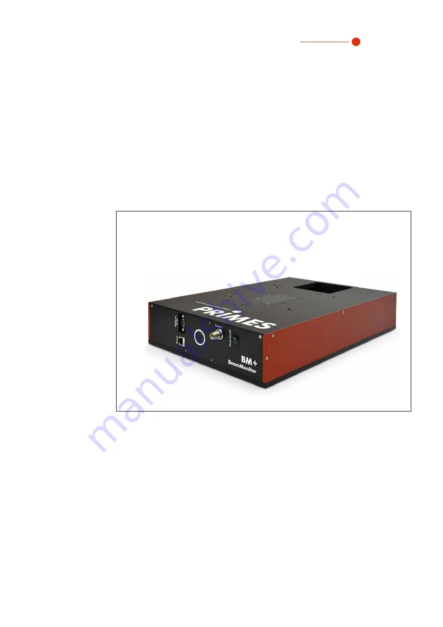
BeamMonitor BM+ 100S
Page 1: ...BeamMonitor BM BM 60 BM 100S LaserDiagnosticsSoftware LDS 35 0 6 Revision 02 EN 02 2022 Original Instructions BeamMonitor BM 100S...
Page 2: ......
Page 3: ...BeamMonitor BM 35 0 6 3 Revision 02 EN 02 2022 IMPORTANT READ CAREFULLY BEFORE USE KEEP FOR FUTURE USE...
Page 4: ...18 8 1 Overview of the connections 18 8 1 1 Connections of the BeamMonitor BM 60 18 8 1 2 Connections of the BeamMonitor BM 100S 18 8 2 Power supply Power In 19 8 3 Ethernet 20 8 4 PRIMES bus RS485 2...
Page 5: ...he measurement results 48 9 6 Linescan 49 9 6 1 Settings 49 9 6 2 Advanced settings 51 9 6 3 Search laser beam automatically with the find beam function 52 9 6 4 Adjust the width length and position o...
Page 6: ...asuring devices to determine the following beam parameters Laser power Beam dimensions and position of an unfocused beam Beam dimensions and position of a focused beam Beam quality factor M PRIMES is...
Page 7: ...particular observe the regulations on laser safety and comply with their requirements Necessary safety measures DANGER Serious eye or skin injury due to laser radiation The device measures direct las...
Page 8: ...hich are direct or indirect con sequences of using the device not as intended or modifying the device or the associated software without authorization 2 Symbols and conventions Warning messages The fo...
Page 9: ...Points to an element described in the text for example an input field 3 About this operating manual This manual describes the installation and operation of the BeamMonitor BM and how to perform measu...
Page 10: ...wer densities A very high signal to noise ratio is achieved thanks to the dynamics of the analog digital converter used Very low intensities are shown with equal precision next to the high peak intens...
Page 11: ...product safety labels 4 5 1 Warning of hand injuries A potential hazard area for hand injuries and device damage is marked with a symbol on the device The measuring tip of the BeamMonitor BM rotates a...
Page 12: ...using the BM 60 as an example 4 6 Scope of delivery and accessories The following parts are included in the scope of delivery of the BeamMonitor BM BeamMonitor BM PRIMES power supply Power cable Patch...
Page 13: ...ing the device stably Chapter 7 on page 14 4 Establish connections Power supply Power In Ethernet PRIMES Bus RS485 Parallel operation of the BeamMonitor BM for example with the laser power meter Power...
Page 14: ...due to scattered or directed laser radiation When the BeamMonitor BM is being operated the irradiation must be fully absorbed behind the measurement zone Fire bricks or other partly absorbing surfaces...
Page 15: ...fields is to be expected This can lead to measurement errors especially when determining the radius using the second mo ment method 7 2 4 Mount the device DANGER Serious eye or skin injury due to las...
Page 16: ...M 35 0 6 16 Revision 02 EN 02 2022 Mount the BeamMonitor BM 60 Beam 4x M6 76 60 316 133 43 212 106 M6 M6 M6 M6 Beam 4x M6 76 60 316 60 133 43 106 212 60 M6 M6 M6 M6 Fig 7 2 Threaded holes on the BeamM...
Page 17: ...tor BM 35 0 6 17 Revision 02 EN 02 2022 Mount the BeamMonitor BM 100S 4x M6 100 100 100 96 63 M6 M6 M6 M6 150 75 75 100 75 292 71 63 4x M6 436 100 M6 M6 M6 M6 Fig 7 3 Threaded holes on the BeamMonitor...
Page 18: ...e device from the laser system 8 Connections Please only use the PRIMES power supply unit and the provided connection cables Please establish all electrical connections and switch on the device before...
Page 19: ...er sup ply is included in the scope of delivery BeamMonitor BM 100S PRIMES power supply Fig 8 3 Connection of the power supply using the BM 100S as an example Harting M12 P PCB THR 2PC 5P LCOD M STR F...
Page 20: ...BM 100S as an example 8 4 PRIMES bus RS485 Another device such as a PowerMonitor PM 48 100 can be connected to the BeamMonitor BM via the RS485 interface PRIMES bus The signal from the PM 48 100 is tr...
Page 21: ...Destruction of the device due to overvoltage When disconnecting the electrical lines during operation with the supply voltage applied voltage peaks occur which can destroy the communication modules of...
Page 22: ...r suitable protective clothing and protective gloves X Protect yourself from laser radiation by separating protective devices e g by using appropriate shielding X In measurement mode a safety distance...
Page 23: ...asuring tip will continue to rotate for a certain amount of time If the rotating measuring tip hits an obstacle the device must be sent in for service to readjust the measuring tip X Do not reach into...
Page 24: ...er On Off switch The optical display see chapter 4 4 on page 11 shows the operating status 2 Start the LDS by double clicking on the program icon in the start menu group or on the desktop icon The sta...
Page 25: ...ring Center assign an IP address to your PC that is in the same address range as the PRIMES device e g 192 168 116 xyz The IP address of your PRIMES device can be found on the identifica tion plate Th...
Page 26: ...dress As a result the connection can be established faster For a connected device both the IP address and the activation of DHCP can be changed Change the IP address of a device as follows 1 Click on...
Page 27: ...modes sections opens Device function Measuring modes 9 3 2 Open a measuring mode The desired measuring mode is selected in the Device control menu The following measuring modes are available Linescan...
Page 28: ...other modes as well For example if you enter a parameter in the Single planes mode it will be automatically applied to all other modes that use this same parameter To transfer a parameter value enter...
Page 29: ...arrow to open the drop down list Use one of the following options X Enter a value in the parameter field and confirm the entry with the Enter key X Use the slider below the input field 3 Click on the...
Page 30: ...To load a configuration click on the icon Save data with an asterisk in the EEPROM of the device All options marked with an asterisk in the Device control menu can be saved in the EEPROM in the devic...
Page 31: ...d message Warnings Non safety critical problems that influence the quality of the measurement results for example are displayed in a yellow window Use one of the following options X Click on the warni...
Page 32: ...ea measurement range thin lines the area to be recorded measurement window thick lines after performing a beam find and during the measurements a false color view of the recorded area To create and mo...
Page 33: ...measurement window meets your requirements Position in mm Use one of the following options to adjust the position of the measure ment window X Enter the x position y position in the corresponding fiel...
Page 34: ...allation of the LDS These and other options for saving loading configurations are de scribed in chapter 9 3 5 Saving options on page 30 Save current parameters X Click this button to save all current...
Page 35: ...following options to set the wavelength of the laser used X Enter a value in the input field X Use the slider below the input field Focal length of focusing optics in mm If several planes of a causti...
Page 36: ...you can move to a defined y position Use one of the following options X Enter a value in the input field X Use the slider below the input field This option is described in chapter 9 3 4 Move axes on p...
Page 37: ...ent window and gain are set automatically If the search is successful the laser beam is displayed in the graphic representation If the beam is not displayed X Check again the correct alignment of the...
Page 38: ...nter the length and width in the cor responding fields X Position the mouse pointer anywhere within the measurement range and drag while holding down the left mouse button Keep the mouse but ton press...
Page 39: ...itch off the laser after the measure ment is completed unless you want to perform further measurements Averaging if enabled The indication shows the measured planes that are used to average a mea sure...
Page 40: ...z in crement away from the previously measured plane 5 Repeat the last step as often as you like Series measurement using z increment spacing The combination of the Time series and z Increment in mm...
Page 41: ...the opened tools see below We recommend checking the quality of the results after a measurement Depending on the results it may seem necessary to repeat the measurement with improved measurement setu...
Page 42: ...during the measurements a false color view of the recorded area To create and move the measurement window X To create a new measurement window position the mouse pointer anywhere within the measureme...
Page 43: ...X Enter a value in the input field X Use the slider below the input field Find beam This option enables an automatic beam search with an automated mea suring window size and measurement The laser bea...
Page 44: ...in the device and is displayed in the LDS Used wavelength in nm To calculate the beam quality factor M the used wavelength must be entered Depending on the display in the option Calibrated wavelength...
Page 45: ...ing window and gain are set automatically If the search is successful the laser beam is displayed in the graphic representation If the beam is not displayed X Check again the correct alignment of the...
Page 46: ...se pointer anywhere within the measurement range and drag while holding down the left mouse button Keep the mouse but ton pressed until the measurement window meets your requirements 3 Use one of the...
Page 47: ...align ment must be performed remotely behind a separating protective equipment The protective equip ment must block the radiation or attenuate it to a non hazardous level 1 Follow the warning message...
Page 48: ...evision 02 EN 02 2022 9 5 6 Display of the measurement results During the measurement data is continuously being read out and displayed in the graphic view Measure ment data is not saved in the projec...
Page 49: ...olor view of the recorded area To create and move the measuring line X To create a new measuring line position the mouse pointer any where within the measurement range Drag while holding down the left...
Page 50: ...individually saved for each device The saving location is the local installation of the LDS These and other options for saving loading configurations are de scribed in chapter 9 3 5 Saving options on...
Page 51: ...d This is stored in the device and is displayed in the LDS Used wavelength in nm To calculate the beam quality factor M the used wavelength must be entered Depending on the display in the option Calib...
Page 52: ...uring line and gain are set automatically If the search is successful the laser beam is displayed in the graphic representation If the beam is not displayed X Check again the correct alignment of the...
Page 53: ...n the measurement area and drag while holding down the left mouse button Keep the mouse button pressed until the length of the measuring line meets your require ments 3 Use one of the following option...
Page 54: ...measurement X Click the Stop Rotation button to stop the rotation of the measuring tip During the measurement the prog ress is shown in the following indica tors Measurement While the indicator is rot...
Page 55: ...ent in the opened tool see below We recommend checking the quality of the results after a measurement Depending on the results it may seem necessary to repeat the measurement with improved measurement...
Page 56: ...on error 1 Restart the software 2 Switch off the supply voltage switch it on again and start another reset cycle 3 Restart the PC Apart from the ambient noise and zero offset no measuring signal is av...
Page 57: ...free cleaning cloths that do not cause scratches This can be e g microfiber cloths or paper towels from the cosmetics sector 4 If these steps are not sufficient please contact PRIMES or your PRIMES di...
Page 58: ...BeamMonitor BM 35 0 6 58 Revision 02 EN 02 2022 13 Declaration of conformity...
Page 59: ...BeamMonitor BM 35 0 6 59 Revision 02 EN 02 2022...
Page 60: ...Determined parameters Beam position Yes Beam dimensions x y Yes Power density distribution 2D 3D Linescan Yes Measurement duration per plane depending on measure ment parameters such as resolution me...
Page 61: ...r BM 35 0 6 61 Revision 02 EN 02 2022 Environmental conditions Operating temperature range 10 40 C Storage temperature range 5 50 C Reference temperature 22 C Permissible relative humidity non condens...
Page 62: ...BeamMonitor BM 35 0 6 62 Revision 02 EN 02 2022 15 Dimensions 15 1 BeamMonitor BM 60 Laserstrahl 316 316 316 133 60 106 76 60 212 83 60 85 4x M6 43 Laser beam...
Page 63: ...BeamMonitor BM 35 0 6 63 Revision 02 EN 02 2022 15 2 BeamMonitor BM 100S Beam 436 436 4x M6 150 138 100 63 96 71 150 146 292 83 60 85 13 Laser beam...
Page 64: ...ing websites https www gnu org licenses old licenses gpl 2 0 en html https www gnu org licenses licenses en html 16 2 Variety of detectors Different detectors are used depending on the application see...
Page 65: ...supply 2 Unscrew four Torx screws T8 from the cover 3 Lift the cover to remove it The detector is located under the cover Torx T8 Torx T8 Torx T8 Torx T8 Fig 16 1 Opened cover of BeamMonitor BM with d...
Page 66: ...6 D D Fig 16 3 Remove the plastic screws from the detector 2 Carefully remove the detector from the position Please do not pull the cables 3 First loosen the golden angle plug A then the black plug B...
Page 67: ...C on the mounting surface of the detector see Fig 16 5 on page 67 2 Connect the cables NOTICE Blocking the rotational disc If the screws are tightened too firmly they might block the rotational disc X...
Page 68: ...BeamMonitor BM 35 0 6 68 Revision 02 EN 02 2022...