background image

87

9

Master Control

9.4

UCNET

UC Surface Device Permissions

UC Surface

设备权限

StudioLive™SeriesIII

Owner’s Manual

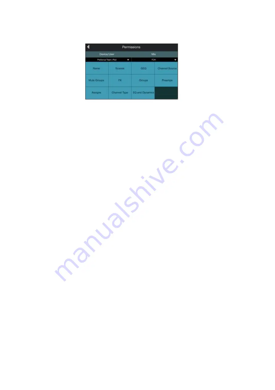
When setting permissions for UC Surface, you can choose to filter out certain

functions. When the button is the off state, the function will not be available for the

selected device.

在为

UC Surface

设置权限时,你可以选择过滤掉某些功能。按钮在关闭状态

时,该功能对所选设备将不可用。

The following functions can be disabled individually:

以下功能可以单独禁用:

• Name.

Enables/disables the ability to remotely change channel and bus names.

启用

/

禁用远程改变通道和总线名称的能力。

• Channel Types.

Enables/disables the ability to remotely change the channel type.

启用

/

禁用远程改变通道类型的能力。

• Channel Source.

Enables/disables the ability to remotely change the channel

source.

启用

/

禁用远程改变通道信号源。

• EQ & Dynamics.

Enables/disables the ability to remotely change EQ and

Dynamics settings for channels and available buses.

启用

/

禁用远程改变通道和可用总线的

EQ

和动态设置。

• Preamps.

Enables/disables the ability to remotely control the preamp functions.

启用

/

禁用远程控制前置放大器功能。

• GEQ.

Enables/disables the ability to adjust the GEQ for the available buses.

启用

/

禁用为可用总线调整

GEQ

• Assigns.

Enables/disables the ability to assign and unassign channels to the main

and subgroup buses.

启用

/

禁用,将通道分配和取消分配到主总线和子群总线的功能。

• FX.

Enables/disables the ability to edit the effects remotely.

启用

/

禁用远程编辑效果的功能。

• Scenes.

Enables/disables the ability to remotely change scenes.

启用

/

禁用远程改变场景的功能。

• Groups.

Enables/disables the ability to remotely create Filter DCA groups.

启用

/

禁用远程创建过滤

DCA

组。

• Mute Groups.

Enables/disables the ability to remotely control mute groups.

启用

/

禁用远程控制静音组。

Summary of Contents for studiolive III series

Page 1: ...www presonus com 3n6lish StudioLiveM Series III Digital Mix Console Recorder with Motorized Faders Owner s Manual...

Page 2: ...Power 19 3 3 TopPanelConnections 19 3 4 TypicalBandSetupDiagrams 20 3 5 TypicalChurchSetupDiagrams 21 4 BasicMixFunctionsOverview 22 4 1 ChannelStripBasics 22 4 2 FaderLayersandBanks 23 4 2 1 UserFad...

Page 3: ...e 68 6 10 2 Input Meters 69 6 10 3 Input Source Routing 69 6 10 4 Polarity and Phantom Power 71 6 10 5 Stereo Link 71 6 11 Output Assignment Buttons 72 6 11 1 Main Mono Bus Assignment StudioLive 64S o...

Page 4: ...tching AES AES 119 12 4 Utilities 120 12 5 SoftPower 120 13 Resources 121 13 1 NetworkingOverview 121 13 1 1 WiredEthernetControlSetup 121 13 2 StereoMicrophonePlacement 123 13 2 1 GrandPiano 123 13 2...

Page 5: ...ange 139 13 10 UsingtheRTAWhileMixing RTA 140 14 Technical Information 141 14 1 Specifications 141 14 2 DefaultRouting 143 14 2 1 InputSource 143 14 2 2 AnalogSends 145 14 2 3 AVBSends AVB 146 14 2 4...

Page 6: ...III Digital Mixe PreSonus Audio Electronics StudioLive StudioLive III PreSonus Audio Electronics 1 2 About this Manual We suggest that you spend some time with this manual before starting to work wit...

Page 7: ...settings We hope these tutorials help you to get the most from your StudioLive Series III mixer Power User Tips StudioLive III All models except the StudioLive 64S are 32 channel mixers and will be r...

Page 8: ...the end In order to achieve this goal we ve prioritized seamless integration throughout every design phase of these products from day one The result is systems that communicate with each other as inte...

Page 9: ...ive III IEC power cord IEC Power User Tip All companion software and drivers for yourPreSonus StudioLive Series III mixerare available for downloadfrom your My PreSonus user account Please visit http...

Page 10: ...al Studio One Artist StudioLive DAW Studio One Studio One Studio One Artist StudioLive UC Surface Reference Manual This guide describes the features and functions of UC Surface with every StudioLive m...

Page 11: ...console mixers can be used to control Studio One and Studio One Artist StudioLive Series III AVB StudioLive Series III AVB StudioLive Series III Fat Channel Plug ins Addendum PreSonus com Fat Channel...

Page 12: ...gital converters are in danger of being overdriven Overdriving the converters will cause digital distortion which has a negative effect on sound quality clip level meters Clipping LED Your P A and stu...

Page 13: ...17 3 19 6 22 8 24 Select Solo Mute Sele Sol Mu Select Solo Select Mute User Prev 5 21 7 23 4 2 Ch 6 6 Ch 7 7 Ch 8 8 Ch 9 9 Ch 10 10 Ch 11 11 Ch 12 12 Ch 10 13 Select Select Select Select Select Select...

Page 14: ...at Channel section Preamp Gain clockwise while watching the Level input meter in the Fat Channel Adjust the Preamp Gain knob until the meter shows an average level around the middle of its range Avoid...

Page 15: ...o the Main output bus Channel 1 Main Channel 1 15 Raise the Main fader while singing or speaking into the microphone until you are satisfied with output level 16 Select the Fat Channel processor Gate...

Page 16: ...to the type of mix you are viewing Aux Subgroup or Matrix StudioLive Select channel Select channel Fat Channel Aux Subgroup or Matrix The Fat Channel is the heart of the StudioLive It gives you a wea...

Page 17: ...Shop Every Fat Channel plug in model can also be loaded in Studio One Purchased plug ins come with both installers included Fat Channel Studio One For more information on loading a purchased Fat Chann...

Page 18: ...User Tip StudioLive III StudioLive 32SC FlexMix FlexMix AVB NSB EarMix For more information on using and configuring FlexMixes seeSection 5 1 FlexMixes 5 1 2 2 4 Fader Layers To provide the most compa...

Page 19: ...oups 4 3 2 2 6 Recording and Playback The StudioLive Series III mixers are equipped with a 34 track SD recorder that is completely integrated with your mixer making multi track recording and Virtual S...

Page 20: ...e stored within a Project A Project saves the mode for each FlexMix Talkback assignments and all the routing set in the Digital Patching menu in addition to System settings like Sample Rate Network Se...

Page 21: ...roject or Scene you can recall it later from any other Project or Scene Fat Channel FX Preset Preset Project Scene Project Scene Reverb Project Scene For more information on saving and loading Fat Cha...

Page 22: ...mbo n a 4 1 4 TRS 2 RCA 1 XLR F AnalogOutputs Flex Mix Subgroup Main Out Mono Center Monitor Out Tape Out 16 XLR M n a 2 XLR M 1 XLR M 2 1 4 TRS 2 RCA 3 1 2 StudioLive 32S AnalogInputs Mic Line Mic On...

Page 23: ...RCA 1 XLR F AnalogOutputs Flex Mix Subgroup Main Out Mono Sum Monitor Out Tape Out 12 XLR M 4 1 4 TRS 4 1 4 TRS 2 XLR M 1 XLR M 2 1 4 TRS 2 RCA 3 1 4 StudioLive 32SC AnalogInputs Mic Line Mic Only Aux...

Page 24: ...XLR 4 1 4 TRS 2 RCA 1 XLR F AnalogOutputs Flex Mix Subgroup Main Out Mono Sum Monitor Out Tape Out 8 XLR M 8 1 4 TRS n a 2 XLR M 1 XLR M 2 1 4 TRS 2 RCA 3 1 7 StudioLive 16 Blue Model DES IG NED AND...

Page 25: ...XLR and balanced or unbalanced 1 4 cables The inch TRS connectors bypass the gain stage and are scaled to accept line level signals up to 18 dBu XMAX TRS XLR XLR 1 4 TRS 18dBu The StudioLive 64S featu...

Page 26: ...turn down a channel s fader before changing connections or toggling phantom power on or off StudioLive Aux Inputs The StudioLive offers two balanced stereo auxiliary inputs While these line inputs ar...

Page 27: ...e FlexMixes on your StudioLive Series III mixer While any FlexMix can be routed to any output by default these mixes are routed in order i e FlexMix 1 to Mix Out 1 FlexMix 2 to Mix Out 2 etc Mix Outpu...

Page 28: ...t the analog stage The Main stereo output attenuation control has a range of 80 to 0 dB The Mono output level control has a range of 80 to 6 dB Main Mono level controls 32 channel models 32 channel St...

Page 29: ...r will not function AES EBU S PDIF adapters contain impedance matching circuitry that is required for proper function Power User Tip AES EBU S PDIF S PDIF XLR RCA AES EBU S PDIF impedance matching Aud...

Page 30: ...ovided to connect a third party console lamp Do not use a bulb that is larger than 12V 380 mA Lamp Connector 12V BNC 12V 380mA console lamp SD Card Slot This slot accepts standard sized SD cards at ca...

Page 31: ...cal mic lead vocal sax acoustic guitar DI backup vocal mics keyboard DI wireless in ear keys wireless router front of house speakers Mobile devices running QMix UC StudioLive control surface wireless...

Page 32: ...UC wireless router laptop running Capture lead and backup vocal mics player wireless in ear front of house speakers wireless in ear lead guitar subwoofers wireless in ear lead vocals wireless in ear k...

Page 33: ...p on your StudioLive apart from the Master features the following controls and visual aids StudioLive StudioLive Master Scribble Strip Display This graphical display shows you useful information about...

Page 34: ...bus Press it again to unmute Level Meter Each channel has a three segment LED level meter to provide an indication of the signal level The bottom segment illuminates when the signal reaches 40 dBFS Th...

Page 35: ...the eight channel strips to the right of the Master fader control FX Returns A D Aux Input 1 2 Tape Input and Talkback The channel strips to the left of the Master fader continue to address input cha...

Page 36: ...aders Press the Prev and Next buttons to scroll through the other available input channels and output buses Prev Next 4 2 1 User Fader Layer The User layer lets you choose a selection of channels that...

Page 37: ...s and hold the Select button for the channel for which you d like to change the assignment This will open the User Layer Assignment screen From here you can unassign the channel completely or change t...

Page 38: ...n a monitor mix and maintain the relative level of the drum mix that you created DCA Filter DCA Filter DCA Once selected a Filter DCA group stays active until exited regardless of which mix is selecte...

Page 39: ...ign channels Select Select Filter DCA Group Select Touch Display 7 Press Done when you ve finished making your channel selections Done Talk DCA 3 3 AUX Inputs Mute Select GEQ Mute 1 You can add and re...

Page 40: ...t on the screen DCA Group DCA Groups master Select Pressing and holding the Select button for a DCA Group master will allow you to add or remove channels from the group by pressing the desired channel...

Page 41: ...Live features a Talkback microphone input on the back panel This can be routed to your choice of Aux outputs as well as the Main output StudioLive Talkback microphone input Aux outputs Main output To...

Page 42: ...t PowerUser Tip While the Talkback has a dedicated rear panel analog input this can be changedandsourced from any Analog AVB USB or SD stream from the Digital Patching menu Inthis way youcan quickly p...

Page 43: ...pre or post main mix level Each channel is equipped with its own level control to create a completely independent mix Aux mixes can be used for many applications The two most common applications are...

Page 44: ...lect button The Select button will cease to illuminate indicating that the function is now locked to the Main Mix To unlock the fader and return to normal functionality press and hold the Select butto...

Page 45: ...mes Bus Panning Stereo Matrix Mixing 5 Aux Pre Mode Aux Matrix FlexMix Aux Channel Send 5 2 5 4 6 FlexMix Mode FlexMix Aux Subgroup or Matrix StudioLive 64S Matrix Mix FlexMixes 17 32 Aux Subgroup Fle...

Page 46: ...nd limiter but before the fader Pre 1 polarity inver Aux bus Pre 2 Fat Channel polarity invert Aux bus Post Sends each channel to the Aux bus after all Fat Channel processing polarity invert high pass...

Page 47: ...ng point adjusting the faders for the relevant channels to create a monitor mix 3 Press the Flex Fader Select button to access the Fat Channel processing for the monitor mix output This can be useful...

Page 48: ...rnal effects processor is similar to creating an internal FX mix only in this case we route the mix signal to a mix output Mix Output 7 in this example and route the effected signal from the processor...

Page 49: ...7 7 For each channel that you wish to send to the external processor move the related fader to the desired level Setting a fader higher makes the related channel sound more processed or wet wet 8 Move...

Page 50: ...bgroup You will find many uses for subgroups that will make mixing more convenient and will provide better control of your mix At the end of this section we explore one of the most common ways in whic...

Page 51: ...across the fader layers when the FlexMix is selected FlexMix FlexMix Channels can be added or removed at any time by pressing and holding the FlexMix button for the desired FlexMix subgroup FlexMix Fl...

Page 52: ...fixed Subgroups master faders press the Mix FX Masters button This will bring up the master output control for every output bus Mix FX Masters Use the Next button to bank to the end of the FlexMixes...

Page 53: ...s are drums backing vocals horn sections and string sections Drums are a classic application for subgroup mixing While we ll use a drum group in this particular example these principles can be applied...

Page 54: ...a good mix of the instruments you are grouping in this case the drums Beginning with Channel 1 Kick raise the fader and with the drummer s assistance set the input trim EQ and dynamics for each drum s...

Page 55: ...of the most common uses Feeding the house mix to multiple locations i e the lobby a webcast feed Creating a front fill mix A note to StudioLive 64S users The Matrix Mixoptionis only available on FlexM...

Page 56: ...ed will be sent to Matrix mixes before the GEQ GEQ GEQ Matrix mixes 5 4 2 Creating a Front Fill Mix Front Fill Mix In some venues the house PA doesn t cover the front rows effectively This can be espe...

Page 57: ...he effect This allows you to add a lot or a little of an effect to any given channel The internal effects buses are used much in the same way the Aux buses are used to create monitor mixes Let s creat...

Page 58: ...to Stereo Pan Mode to change this to LCR Pan Mode press the Home button StudioLive 64S Pan LCR Pan Home 2 Press the System icon to open the System menu System System menu 3 From this menu you can tog...

Page 59: ...only the channels you want in your subwoofers you can achieve a much cleaner sub frequency mix This also allows you to send less low frequency content to your full range system and to create more clar...

Page 60: ...our subwoofer Or less keys This is where the Mono send comes into play allowing you to customize your low frequency mix to better enhance your system If you need even more control you can set the send...

Page 61: ...To adjust the Center Divergence scroll to the second page of the Fat Channel Input layer and use the encoder below the Center Divergence display The Center Divergence control has a range from 0 to 10...

Page 62: ...Pan C When the Center Divergence control is set to 100 and the channel is panned to center C the entire signal will be sent to the Center bus and none will be sent to the Left or Right sides of the Ma...

Page 63: ...master faders available on the channel strips Then you can press the Select button that corresponds with the mix or bus you want to work with bringing it into focus in the Fat Channel Bank Mix FX Mast...

Page 64: ...ected channel as the A snapshot and copies its settings to a second snapshot we ll call B The A B button lights to tell you that you are now working with the B snapshot A B Fat Channel A B A snapshot...

Page 65: ...ntly selected channel Copy Fat Channel Copy Select Select Press Load to paste the settings to the selected channels Load The Save and Load buttons let you save and load Fat Channel presets letting you...

Page 66: ...Drum Guitar 3 Press the Enter button on the keyboard to save your preset or press the back arrow to cancel and exit this screen Enter Enter 1 Press Load The Fat Channel Presets view is shown on the To...

Page 67: ...gs are included when copy pasting or loading presets press Advanced Filtering to open the Copy Paste Preset Filtering screen In this screen you can set the exact parameter types that are included in e...

Page 68: ...ve 32SX and StudioLive 32SC always control the following functions StudioLive 32SX StudioLive 32SC 1 AGC Automatic Gain Compensation 2 Preamp Gain 3 Center 4 Pan 5 Gate On Off 6 Gate Threshold 7 Compr...

Page 69: ...46...

Page 70: ...ompressor Overview 6 5 6 8 4 5 EQ For all StudioLive models this opens the EQ Overview screen on the Touch Display For models equipped with a Dynamic Fat Channel this button will spill the EQ controls...

Page 71: ...ld The pan position will be displayed on the Scribble Strip Press the button below the encoder to reset the pan position to Center subgroup Pan Scribble Strip Pan 3 Gate Threshold The encoder sets and...

Page 72: ...h Mid Band B3 for control B3 8 EQ Q Sets the Q or width of the current EQ band Larger Q values affect a narrower range of frequencies Lower Q values affect a wider range Press the button below to enab...

Page 73: ...er Divergence percentage Pre Post fader Mono Bus 5 6 3 Delay Sets the alignment delay for the currently selected input or bus More information about input and output delays and be found in Section 13...

Page 74: ...tthe attack and release times correctly More information about Gates and Expanders can be found at www presonus com learn technical articles How To Use Dynamics Processing Getting Started With Compres...

Page 75: ...ey Listen function in the solo bus It will illuminate to indicate that the Key Listen is active When Key Listen is enabled and the selected channel is soloed you can use the Control Room outputs to mo...

Page 76: ...hannel by default Dynamic Fat Channel Controls Fat Channel Controls 1 2 3 4 5 6 7 COMP Key Fltr Off Key Lstn COMP Attack 20 00 ms Auto COMP Off Soft COMP Release 150 ms COMP Thresh 0 00 dB COMP Gain 0...

Page 77: ...er compression occurs makeup gain 6 Compressor Knee Soft Hard Press this button to toggle the compressor between soft and hard knee modes Soft knee compression offers a smooth transition between uncom...

Page 78: ...n reduction and more pronounced compression effect 3 Compressor Limiter Toggle The button below toggles the Tube Leveling Amplifier between its compressor and limiter modes When in compressor mode it...

Page 79: ...ck up to the proper level after compression occurs makeup gain 3 Attack Sets the time it takes for the compressor to begin attenuating a signal once it passes the threshold 4 Release Sets the time it...

Page 80: ...D Freq 1 40 kHz Q Freq LOW Gain 0 00 dB On Off L MID Gain 0 00 dB On Off HIGH Gain 0 00 dB On Off 1 Band 1 Low Gain Sets the amount by which the selected frequency will be boosted or cut Press the but...

Page 81: ...7 Band 4 High Gain Sets the amount by which the selected frequency will be boosted or cut Press the button below to turn the band on or off 8 Band 4 High Frequency Q The encoder can control either fre...

Page 82: ...lowing for boosts in apparent bass energy while keeping overall bass energy within optimal limits Low Boost 3 Low Frequency Select Sets the center frequency of the band covered by the Low Boost and Lo...

Page 83: ...ng 3 L Mid Gain Sets the amount of boost or cut to apply the low mid frequency band of this EQ 4 L Mid Frequency Sets the center frequency of the low mid frequency band of this EQ 5 H Mid Gain Sets th...

Page 84: ...oder controls the send level of the channel to the Stereo Aux The button beneath controls the channel mute in the Stereo Aux Stereo Aux 3 Stereo Aux Pan The encoder controls the pan position of the ch...

Page 85: ...Displays the EQ overview Touch to open the EQ Screen See Section 6 6 for more information EQ 6 6 5 Name Displays currently selected channel or bus name 6 Current Parameter Displays currently controlle...

Page 86: ...er High Pass Filter cut off Master Control encoder Note The Mainstereo and Mono bus on the StudioLive 64S provides a toggle betweenLow Pass Filter andHigh Pass Filter behavior StudioLive 64S Mainstere...

Page 87: ...nel Color Sets the color of a channel s Select button If no color is selected the Select button will be blue Select Select 5 Stereo Link Options These options let you specify the linking behavior when...

Page 88: ...e in a linked pair is reflected in the other linked channel PowerUser Tip Ifone of the digital inputs Network USB or SD is selected as the channel source youwill be presented with the option to design...

Page 89: ...6 4 1 for details 4 18 17 16 15 14 13 5 6 7 8 9 Fat Channel Gate Touch Display Gate Overview Gate Master Control encoder Master Control PowerUser Tip Fat Channel StudioLive FatChannel 6 4 1 1 Signal...

Page 90: ...Displays the amount of Gain Reduction applied by the Gate to the channel Gate Gain Reduction 12 Graph Displays the Gate curve Gate curve 13 Input Meter Displays the pre Gate signal level pre Gate 14 R...

Page 91: ...er A model of a Class A FET based compressor with an aggressive punchy tonal character FET A In addition to the three plug in models that come with your StudioLive mixer the following additional compr...

Page 92: ...out uneven volume fluctuations Emulating an all tube optical design the Tube P1B compressor delivers musicality preserving the clarity of the signal even at the most extreme settings Included in the V...

Page 93: ...parameter and its value 5 Presets Opens Presets menu on the Touch Display Touch Display Presets 6 Compressor Type Changes the type of Compressor model Compressor 7 Comp EQ The Compressor and EQ can b...

Page 94: ...Compressor Compressor 3 Ratio Sets the Compressor Ratio 4 Attack Sets the Attack time for the Compressor Attack time 5 Gain Sets Make up Gain for the Compressor Compressor 6 Release Sets the Release...

Page 95: ...ter Control Master Control Power User Tip For StudioLive models with dynamic Fat Channel displays many of these parameters can also be controlled from the encoders and buttons in the Fat Channel See S...

Page 96: ...ssor Compressor 2 Input Sets the input gain to the compressor Compressor 3 Output Sets the make up gain for the compressor Compressor 4 Attack Sets the attack time for the compressor Compressor attack...

Page 97: ...ion using three overlapping bands divided into seven fixed frequency points each with five steps of boost or cut Its selectable peaking or shelving filters for the high and low band along with an inde...

Page 98: ...en bite Vintage Channel Strips Bundle VT 1 EQ The VT 1 EQ models a popular vacuum tube channel strip s 4 band semi parametric EQ which combines isolated filters and optimized per band Q Designed with...

Page 99: ...nges to the EQ settingswithoutneeding to alter the compressor setting However if you place the EQ before the compressor youcanbetter controldifferentfrequencies achieving a more natural response EQ EQ...

Page 100: ...Q 3 Gain 1 Frequency 2 Q 3 Band 1 6 Band 1 On Off Enables disables Band 1 Band1 7 Band 2 Select Selects Band 2 for control via Gain 1 Frequency 2 and Q 3 Gain 1 Frequency 2 Q 3 Band 2 8 Band 2 On Off...

Page 101: ...quencies at and below a user selected shelving frequency low shelf EQ Shelf Low band Shelf Low band low shelving EQ Power UserTip A low shelvingEQ is like a bass control knob on a stereo In this mode...

Page 102: ...High Band High Band 9 Attenuation Select Sets the Frequency at which the attenuation begins Frequency 6 8 5 3 Vintage 1970s EQ Overview Screen 1970 EQ When the Fat Channel is in Vintage EQ mode the To...

Page 103: ...ets the center frequency for the High Mid Band 7 High Mid Gain Sets the Gain for the High Mid Band 8 High Gain Sets the Gain for the High Band 1 EQ On Off 2 Low Frequency 3 Low Gain 4 Low Mid Frequenc...

Page 104: ...ate your own custom Fat Channel controls To assign a function to an encoder and its adjacent button press any unassigned button This will open the User Mode edit screen User Mode Fat Channel User Mode...

Page 105: ...pressing and holding any of these buttons you ll enter Multi Assign mode which allows you to set the input source for multiple channels at once Once in this mode the Select button for every Input Chan...

Page 106: ...can select the sources for the different input types available for the currently selected channel or bus Overview Input Source Input Source Screen By default every input source is routed to its respec...

Page 107: ...ip It is importantto understandthat for output buses this is the input to the bus not the output itself In most instances this will be sourced fromthe internal DSP This feature can be used to insert a...

Page 108: ...ct the SD Track that will be active on the currently selected channel or bus when the source is set to SD in the Fat channel Tap on any SD playback stream to patch it to the current channel SD Input S...

Page 109: ...d channel Channel 1 2 7 8 The following parameters are always kept in parity between linked channels or buses Input assignment Channel type Bus mode aux subgroup aux Compressor EQ type Gate parameters...

Page 110: ...71 Channel bus names For more information on selecting linking options seeSection 6 8 2 6 8 2...

Page 111: ...ons to assign it to an output path Press Main to send the selected channel output to the Main bus Press SubGrp to open the Bus Assignment screen on the Touch display Main Main SubGrp Touch display Bus...

Page 112: ...t channel from the following options Tape Edit Tape input Analog BT Touch this button to route both the Tape input jacks and the currently selected paired Bluetooth device to the Tape input channel Wh...

Page 113: ...audio device for use with the Tape input Press and hold the Bluetooth button in the Tape control area for two seconds to enter pairing mode The button will flash indicating that your StudioLive is sea...

Page 114: ...D SDHC card and test your SD SDHC card s speed SD SD SDHC SD SDHC Before beginning any multitrack recording it is recommended that you format your SD SDHC card in FAT32 format even if your card was fo...

Page 115: ...Display Artist Performance Location When you ve entered the artist name performance name or location for one Session it is saved for easy use in future sessions up to 10 of each category at a time Sa...

Page 116: ...your Session Capture When the Load Mix button is active the mix Scene stored with the session will also load The parameters that are loaded are filtered according to the settings in the Scenes screen...

Page 117: ...Select Select A note to StudioLive 64S Users Because SD recording is limited to 34 tracks any channel on your StudioLive 64S can be routed to any of the 34 tracks in your Capture SD session Because o...

Page 118: ...nd Close Saves the session and returns to the Live Recording Edit screen Edit 8 3 1 Recording Status Messages Status The following indicators on the Capture screen will help you to keep an eye on how...

Page 119: ...ccur you will hear a skip or a drop out in the recorded audio Power User Tip As soon as you see an error display make a note of the current timeline position This will help you to isolate the audio dr...

Page 120: ...This will launch the Load Session screen Select the previously recorded session you would like to use for your Virtual Soundcheck Load Session 3 The Recall button will begin to flash Press the Recall...

Page 121: ...quipped with internal effects processors loaded with models of classic reverb units delays and modulation effects Each processor is equipped with its own internal effect bus Every channel on your Stud...

Page 122: ...old Tap and adjust the control of your choice to return that control to its default setting Power User Tip Fat Channel Graphic EQ FX null Tap If you have just one effects slot occupied by a delay effe...

Page 123: ...orus Flanger 1 2 3 4 1 FX Slot Displays the currently selected FX Slot FX Slot 2 Effects Type Menu This drop down menu allows you to change the active effect currently selected FX Slot FX Slot 3 Prese...

Page 124: ...er the room will seem Size Sets the width of the stereo image LPF Frequency Use this control to attenuate low frequencies that can muddy a reverb LF Damping Freq Use this control with create a warmer...

Page 125: ...he level in decibels of the early reflections The louder the early reflections the smaller the room will seem Size Sets the width of the stereo image Low Pass Use this control to attenuate low frequen...

Page 126: ...early reflections The louder the early reflections the smaller the room will seem Low Pass Use this control to attenuate low frequencies that can muddy a reverb LF Damp Freq Use this control with crea...

Page 127: ...ller the room will seem Low Pass Use this control to attenuate low frequencies that can muddy a reverb LF Damp Freq Use this control with create a warmer sound This will enhance content at the frequen...

Page 128: ...signal HP Filter Sets the cutoff frequency for a high pass filter applied to the delayed signal Feedback LPF Sets the cutoff frequency for the low pass filter applied to the feedback signal Feedback H...

Page 129: ...ive inputs of the effect Higher settings lead to longer delay tails and eventually outright chaos Spread Sets the width of the stereo image LP Filter Sets the cutoff frequency for a low pass filter ap...

Page 130: ...f delayed signal fed back into the input of the effect Fb Time Sets the delay offset of the feedback signal LP Filter Sets the cutoff frequency for the low pass filter on the delayed signal HP Filter...

Page 131: ...es the polarity between positive off and bi polar on Shape Sets the type of wave form for the LFO LFO Offset Sets the time in milliseconds between the source signal and the modulated signal Feedback V...

Page 132: ...conds between the source signal and the modulated signal Feedback Variable feedback or regeneration produces multiple decaying repeats Increasing the feedback value increases the number of echoes as w...

Page 133: ...tion Selecting a previously stored preset will overwrite the stored settings with the current settings 2 Press the Store button in the Master Control area to bring up the onscreen keyboard Enter your...

Page 134: ...ly audition the effects of a preset by selecting a preset and pressing the Audition button on the Touch Display or rename it by pressing Rename and entering a new name with the onscreen keyboard Touch...

Page 135: ...creen you will fix the name of your mixer You can customize your Mixer s name by tapping on the Mixer Nickname field This will change the mixer s name anywhere it is displayed UC Surface QMix UC etc U...

Page 136: ...on to choose from QMix UC Mix None Select this to disable remote control on the selected device All Mixes Control of every Aux Mix Send level and pan setting Aux Mix Send pan Mix X Control of an indiv...

Page 137: ...Enables disables the ability to remotely change the channel source EQ Dynamics Enables disables the ability to remotely change EQ and Dynamics settings for channels and available buses EQ Preamps Ena...

Page 138: ...oTools StudioLive III Studio One Logic Mackie ProTools HUI For more information on using your StudioLive mixer as a controller for your DAW application please review the following addendums StudioLive...

Page 139: ...you need to change it In this mode an Apply button is shown Touch this button to auto assign a new static IP address to your StudioLive IP Apply StudioLive IP Static Manual The IP address can be set...

Page 140: ...StudioLive mixer as a controller for your DAW application please review the following addendums StudioLive DAW StudioLive Series III Studio One DAW Control Addendum StudioLive Series III MCU for Logic...

Page 141: ...ing addendums StudioLive DAW StudioLive Series III Studio One DAW Control Addendum StudioLive Series III MCU for Logic DAW Control Addendum StudioLive Series III HUI Emulation for ProTools DAW Control...

Page 142: ...PFL Solo Level PFL Global Options Peak Hold Link Aux Mute Mode Link Aux Mute Mode AUX Monitor Options Phones Cue Source Network IP Address Settings Dynamic Self Assign or Manual Digital Patching Inpu...

Page 143: ...he keyboard Touch Display Store Project 4 Press the Enter button to save your Project or press the Cancel button on the screen to cancel and return to the Projects Library screen Enter Project Cancel...

Page 144: ...studio saving and recalling a scene allows you to move to another song and come back to the current mix later For live shows with multiple bands you can set up custom mixes for each band at soundcheck...

Page 145: ...splay Scenes library Store Recall 3 Scroll to an empty Scene location and press the Store button in the Master Control area or on the right side of the screen to enter a custom name Scene Master Contr...

Page 146: ...d USB SD USB FX Mix Pre Post Modes Pre 1 Pre 2 or Post Settings for all FX Mixes FX Pre 1 Pre 2 Post Settings General Settings Peak Hold Link Aux Mute Mode Phones Cue Source Network IP Settings Peak H...

Page 147: ...olo in Place Solo Selects Solo PFL Solo Level PFL Analog Input Patching The Analog Input Patching set in the Digital Patching menu Digital Patching Analog Input Patching SD Patching The SD Patching se...

Page 148: ...Phantom Power Polarity Output Fat Channel FatChannel FatChannelSettingsforallOutputs High Pass Low Pass Filter Compressor Settings EQ Settings FatChannelOrder EQ Comp LimiterSetting Main Mix Level Th...

Page 149: ...you can choose to rename it lock it or delete it entirely Projects list To rename a Project tap the edit field Tapping on the Lock button will prevent overwriting the stored parameters Lock Tap the D...

Page 150: ...ct Delete Scene You can also tap on the X next to a Scene in the Edit List to remove it from the Project Power User Tip Your StudioLive mixer will always ask you to confirm your selection beforeitdele...

Page 151: ...s not necessary to create a scene for your StudioLive in order to preserve its settings when you power it down The StudioLive takes continuous snapshots of the current position of every parameter on t...

Page 152: ...o Mode SoloLevel Unity Phones Cue Source Solo Peak Hold Off SampleRate 48kHz Link Aux Mute Mode Unlinked Network IP Mode Dynamic Transport Controls SD Card GEQ No Assignments Note See Section 14 2 for...

Page 153: ...t your scene Thisis the easiestway to ensure that there are no lingering parameter settings that could cause you some trouble in your new mix Power User Tip 9 6 7 Nulling Parameters To return any Fat...

Page 154: ...s the Phones button to do so for the headphone output In either case a grid of available sources is shown Solo Main Tape FlexMixes Touching any one of these sources routes it to the currently selected...

Page 155: ...al with the fader This is the StudioLive s default setting AFL StudioLive PFL Pre Fader Listen PFL sends the channel or subgroup signal to the Solo bus before it reaches the fader so the fader does no...

Page 156: ...l this mode should be used with extreme caution during a live performance Only the input channels can be placed in destructive soloing The subgroups and aux buses are omitted from SIP mode Solo In Pla...

Page 157: ...s Radio Solo 6 Solo Modes Defaults to Radio mode These buttons let you choose from the following behavioral modes for channel soloing Radio Latch In this mode you can solo multiple channels or buses a...

Page 158: ...e it if you want channel levels to be affected by fader levels Pre Fader Listen 3 Touch Latch in the Solo Mode section of the Touch Display to enable the Latch solo mode This lets you solo multiple ch...

Page 159: ...Live SIP 1 Press the Edit button in the Solo section to bring up the Solo screen Edit Solo 2 Touch Radio in the Solo Mode section of the Touch Display to enable Radio Solo mode Touch Display Solo Mode...

Page 160: ...and touch Solo in Place on the Touch Display to disable it and set up your fader mixer Touch Display Solo in Place Power User Tip While Radio Solo mode is especially useful for setting levels as desc...

Page 161: ...m to round out your final mix To assist you with these adjustments here is an overview of the way different frequency ranges affect sound characteristics dead live Sub Bass 16 Hz to 60 Hz The lowest o...

Page 162: ...responsible for the clarity of a mix and provides a measure of control over the perception of distance If you boost this frequency range the mix will be perceived as closer to the listener Attenuating...

Page 163: ...access the GEQ at any time by pressing the GEQ button on your desired mix GEQ GEQ Use the Fat Channel encoders to control the Graphic EQ in banks of eight Use the Master Control encoder to scroll to a...

Page 164: ...4 StudioLive 32SX and 32SC Users Power User Tip For StudioLive 32SXand 32SC users theRTA canbe enabledand disabledfromthe control surface by pressing the RTA button StudioLive 32SX 32SC Power User Ti...

Page 165: ...cancel the process GEQ GEQ Presets GEQ Recall GEQ Store Save Cancel 11 4 Using the RTA to Ring Out Monitors RTA Every Graphic EQ is equipped with a Real time analyzer or RTA in which x frequency and y...

Page 166: ...age monitors will produce feedback Ifyou are not careful you can produce a lot offeedback Do not make sudden gain boosts go slowly and carefully to avoid causing any damage to speakers and ears Ringin...

Page 167: ...ain system feedback is typically in the mid to low range The frequencies that are regenerating and creating a feedback loop are those frequencies that are wrapping around the main system due to the lo...

Page 168: ...ion 12 1 12 1 3 User Profiles Lets you create custom profiles and grant access to select feature to certain users while locking others For more information see Section 12 2 12 2 4 Capture Lets you rec...

Page 169: ...kback Edit Opens the Talkback Edit page For more information see Section 4 5 1 Talkback Edit 4 5 1 10 Selected Channel Displays currently selected channel or bus 11 Current Parameter Displays current...

Page 170: ...ption on to enable peak hold mode for the various meters throughout StudioLive When enabled an indicator segment is lit on each meter showing the highest point in the amplitude scale that the related...

Page 171: ...are and offers functions for installing firmware updates For more information see Section 12 1 4 StudioLive 12 1 4 11 Permissions Lets you configure StudioLive control permissions for any connected co...

Page 172: ...NET screen For more information on setting mixer permissions seeSection 9 4 2 System Permissions UCNET 9 4 2 12 1 2 User Buttons Assigns Every StudioLive Series III mixers feature eight user assignabl...

Page 173: ...108 Press the Edit button that corresponds to the User Button you want to edit and you ll see a function assignment screen User Button Edit...

Page 174: ...Tap Tempo it will flash in time with tempo of its assigned delay User Button tap tempo User Button tap tempo Quick Scene Lets you create stored sets of mixer settings that correspond with the current...

Page 175: ...settings are available to toggle on or off Preamp Filtered by default 48V Filtered by default Polarity Filtered by default Pan Channel Type Channel Name Alt A B Settings Bus Assignments Filtered by de...

Page 176: ...ce UC Surface 12 1 5 Link Aux Mutes Aux Mutes Pressing the Link Aux Mutes button from the System menu lets you select between four linking modes that choose the way channel mutes and Aux send mutes in...

Page 177: ...ofiles allow you to create custom settings limiting access to certain functions Specific scenes can also be assigned to each Profile so that when the user logs into the mixer they will have the option...

Page 178: ...strator 12 2 2 2 Default Project Tap to open a list of all available projects Once a project is selected you will be ask if you d like to load it when you log in as the Default Administrator 3 Default...

Page 179: ...111 Tap password Default Administrator Default Administrator password Master Mute 5 Reset Profile Resets profile to default state...

Page 180: ...e default name field to enter a custom profile name The only name that cannot be changed is the Default Administrator Touch the Enter button when done Touch Cancel to leave the name unchanged Default...

Page 181: ...file Default Project Scene screen From here you can select the Default Project and Scene Default Project or Scene User Profile Default Project Scene screen Default Project and Scene Note While anyProj...

Page 182: ...113 Reset Profile To reset a profile to factory default select Reset Profile You will be prompted to confirm this choice Reset Profile...

Page 183: ...functions on a per User basis Edit Permissions Channel Bus Names This locks the ability to rename any Channel or Bus Channel Types This locks the ability to change the Channel Type Channel Type Input...

Page 184: ...ve or create new scenes Changing Adding DCA Filter Groups This locks the ability to create or alter DCA Filter Groups DCA Filter Groups Whenever a User attempts to access a function to which they do n...

Page 185: ...ive AVB Networking Guide for more information StudioLive AVB StudioLive AVB Stagebox Setup Touch to configure NSB series Network Stage Boxes or StudioLive Series III rack mixers as stage boxes with yo...

Page 186: ...audio to your AVB network and record anything you d like via USB Digital patching Digital patching AVB USB Press Master Reset to revert all Digital patching for the entire mixer to the default settin...

Page 187: ...back Returns SD Whatever source type you ve selected a corresponding list of inputs will open in the Available Source menu From this menu you can for example route Analog Input 10 to Channel 1 Availab...

Page 188: ...Available Source list Press the reset button to repatch the default routing reset You can route any of the following mixes to physical mix outputs on your StudioLive mixer StudioLive FlexMixes FX Send...

Page 189: ...from the Available Source list to the right AVB Sends menu AVB send Available Source Press the reset button to repatch the default routing reset The following local StudioLive sources can be sent out...

Page 190: ...right Press the reset button to repatch the default routing USB Sends menu USB driver send USB driver send Available Source list reset The following local StudioLive sources can be sent to the USB bus...

Page 191: ...Then select the channel or mix from the Available Source list to the right StudioLive 64S SD Card 34 SD Card SD Card Available Source All other users Selecting the SD Card menu will allow you to patc...

Page 192: ...Causes all color changing buttons to cycle through their ranges of color and brightness Scribble Strip Causes all scribble strip displays to cycle through a range of color test patterns scribble stri...

Page 193: ...ely and control most of your mixer settings or add a second screen to your system More information on Control Networking options can be found in Section 9 4 StudioLive iPad UC Surface QMix UC iOS Andr...

Page 194: ...ersal Control 3 When Universal Control launch window appears Tap on your mixer s icon to launch UC Surface Universal Control UC Surface For more information on UC Surface see the UC Surface Reference...

Page 195: ...ame of the wireless network you set for your wireless router 3 Enter the password 4 Click Join Note Information on connecting your iOS device to the wireless network can be found in the Networking for...

Page 196: ...rding StudioLive 13 2 1 Grand Piano Place one microphone above the high strings and one microphone above the low strings Experiment with distance the farther back the more room you will capture This t...

Page 197: ...microphones See drum overheads picture on the next page 12 8 12 XY 13 2 4 Bass Guitar Direct and Speaker Plug the electric bass guitar into a passive direct box Connect the instrument output from the...

Page 198: ...r 8 feet above the floor or drum riser Experiment with height This technique can be used in live applications as well XY 45 7 8 13 2 6 Snare Drum top and bottom Point a dynamic microphone at the cente...

Page 199: ...moves the vocal more up front in the mix Medium Soft THRESHOLD RATIO ATTACK RELEASE 3 3dB 2 8 1 0 002ms 38ms Screamer This setting is for loud vocals It is a fairly hard compression setting for a voca...

Page 200: ...HOLD RATIO ATTACK RELEASE 0 1dB 2 4 1 26ms 193ms 13 3 4 Keyboards Piano This is a special setting for an even level across the keyboard It is designed to help even up the top and bottom of an acoustic...

Page 201: ...ression for solo work especially electric guitar It gives you that glassy Tele Strat sound It is a true classic Tele Strat THRESHOLD RATIO ATTACK RELEASE 4 6dB 2 4 1 7 2ms 93ms Pump This is a setting...

Page 202: ...ddy 125Hz Bottomend Acoustic Guitar 2 3kHz Tinny 5kHzandabove Sparkle 200Hz Boomy 125Hz Full ElectricBass 1kHz Thin 600Hz Growl 125Hz Boomy 80Hzandbelow Bottomend StringBass 600Hz Hollow 2 5kHz Sharpa...

Page 203: ...sound bass line clarity especially for softer playback levels vocalfullness hardhittingsnare andguitar decrease bass boom to increase clarityinthemix decrease dullnessin guitars bass line clarity and...

Page 204: ...FREQ Hz LOW Q LOW GAIN LOW MID ON OFF LOW MID FREQ Hz LOW MID Q LOW MID GAIN ON OFF 130 0 6 4 ON 665 0 5 4 HIGH MID ON OFF ON HI MID FREQ kHz 1 6 HIGH MID Q 0 3 HIGH MID GAIN 4 HIGH ON OFF ON HIGH SH...

Page 205: ...2 0 2 HIGH MID ON OFF HI MID FREQ kHz HIGH MID Q HIGH MID GAIN HIGH ON OFF HIGH SHELF HIGH FREQ kHz HIGHQ HIGH GAIN ON 2 0 0 3 0 ON ON 6 0 N A 4 Distorted Electric Guitar LOW ON OFF LOW SHELF LOW FREQ...

Page 206: ...create a more coherent signal This is especially useful to prevent phasing problems 13 6 1 Aligning the Backline with Vocal Mic In this example we will delay the guitar amp s close mic to its arrival...

Page 207: ...ls being out of phase with respect to each other This problem can sometimes be corrected by alternatively flipping polarity on the direct and microphone channels to find which combination of the two s...

Page 208: ...el PowerUser Tip The finalresultmay notbe perfectly in time but this is not necessarily your goal Adjusting the phase relationship between the direct and mic d signals can help to create space in a mi...

Page 209: ...and little careful listening this can be dialed in without extra accessories 13 7 1 Front of House In a small venue with a relatively small stage both the main speaker system and the acoustic level of...

Page 210: ...Front of house system as closely to the acoustic level of the snare drum as possible Main mix level 5 Listen closely to the speakers and the snare and make minor adjustments to the output delay until...

Page 211: ...cles Inside Indoors you are trying to overcome the direct to reverberant reflections Your goal is to find where the direct signal to reverberation ratio has reached about 50 50 At this point the refle...

Page 212: ...o match the output of the main and delay systems at the measurement point For example if you are standing 30 feet from the left side of the main system and 10 feet from the left side of the delay syst...

Page 213: ...e smaller distance the distance to the subwoofer from the larger distance the distance to the full range loudspeaker 4 Divide the distance by 1 1 if measured in feet or 0 34 if measured in meters and...

Page 214: ...ilter attack release This tutorial will guide you through the first use case Please note that while sidechaining the kick drum to the bass channel can tighten up a good rhythm section and make them so...

Page 215: ...ship attack release key source Bringing Out the Kick Drum In some instances a synth bass line or a busy bass guitar part interferes with the kick drum presence and punch in the mix For this applicatio...

Page 216: ...edge of the stage and shout Hello world toward the center of the hall There will be a brief pause before you hear the first noticeable reflections of your voice because the sound waves can travel muc...

Page 217: ...empo StudioLive Tap Tempo PowerUserTip While you have to select the Time parameter in order to use the Tap button youonly have to do this thefirst time youuse the Tap buttonfor thateffect Once the Tap...

Page 218: ...a low frequency oscillator or LFO to vary the pitch and timing of the delay signal The two most common modulation effects are chorus and modulation low frequency oscillator LFO chorus modulation Simi...

Page 219: ...on problem areas makes the RTA a secret weapon for many a mix engineer The RTA also lends itself very well to ear training and gives you confidence that you are choosing the right frequencies when ma...

Page 220: ...onseto MainOutput at unitygain 20 20 kHz 0 5 dBu Input Impedance 10 k THDto MainOutput THD 0 005 4 dBu 20 20 kHz unity gain unwtd S N Ratioto MainOutput Ref 4dB 20 kHz BW unitygain A wtd 4dB 20kHzBW u...

Page 221: ...2 bit oating point Sampling Rate 48 kHz A D A Bit Depth A D A 24 Reference Levelfor0 dBFS 0dBFS 18dBu Total System Latency 1 9 ms local routing analog in analog out all processing active Clock Jitter...

Page 222: ...5 Analog15 Analog15 Analog15 Analog15 Analog15 Channel16 Analog16 Analog16 Analog16 Analog16 Analog16 Analog16 Analog16 Channel17 Analog17 Analog17 Analog17 AVB 17 Analog17 Analog17 AVB 17 Channel18 A...

Page 223: ...turn C L R FX Return C L R FX Return D L R FX Return D L R FX Return D L R FX Return D L R FX Return D L R FX Return D L R FX Return D L R FX Return D L R FX Return E L R FX Return E L R FX Return F L...

Page 224: ...exMix3 FlexMix3 FlexMix3 FlexMix3 FlexMix3 FlexMix3 FlexMix3 Mix Out 4 FlexMix 4 FlexMix 4 FlexMix 4 FlexMix 4 FlexMix 4 FlexMix 4 FlexMix 4 Mix Out 5 FlexMix5 FlexMix5 FlexMix5 FlexMix5 FlexMix5 Flex...

Page 225: ...Channel20 Channel20 Channel20 Channel20 AVB Send 21 Channel21 Channel21 Channel21 Channel21 Channel21 Channel21 Channel21 AVB Send 22 Channel22 Channel22 Channel22 Channel22 Channel22 Channel22 Channe...

Page 226: ...SBSend3 Channel3 Channel3 Channel3 Channel3 Channel3 Channel3 Channel3 USBSend4 Channel4 Channel4 Channel4 Channel4 Channel4 Channel4 Channel4 USBSend5 Channel5 Channel5 Channel5 Channel5 Channel5 Cha...

Page 227: ...3 Channel33 AuxIn1Left AuxIn1Left AuxIn1Left AuxIn1Left AuxIn1Left AuxIn1Left USB Send 34 Channel34 AuxIn1Right AuxIn1Right AuxIn1Right AuxIn1Right AuxIn1Right AuxIn1Right USB Send 35 Channel35 AuxIn2...

Page 228: ...D Track 16 Channel16 Ch 16 Fixed Ch 16 Fixed Ch 16 Fixed Ch 16 Fixed Ch 16 Fixed Ch 16 Fixed SD Track 17 Channel17 Ch 17 Fixed Ch 17 Fixed Ch 17 Fixed Ch 17 Fixed Ch 17 Fixed Ch 17 Fixed SD Track 18 C...

Page 229: ...x button in the Mix Select section then try moving channel faders up and down to see if their movement affects the overall output volume as shown by the main output meter If not make sure that your ch...

Page 230: ...ntrols Not Changing Routing Verify that your monitors are connected to the Control Room outputs on the rear panel of your StudioLive not the Main outputs StudioLive Control Room outputs Main Fader Doe...

Page 231: ...and set aside to drain 13 Serve with brown gravy over rice Serves 12 This recipe will make approximately 24 garfish balls Balls can be frozen at step 8 Do not freeze cooked patties 24 8 Garfish have a...

Page 232: ...StudioLive Series III Digital Mix Console Recorder with Motorized Faders Owner s Manual 18011 Grand Bay Ct Baton Rouge Louisiana 70809 USA 1 225 216 7887 www presonus com Part 70 22000045 F...

Reviews: