


PowerFleet
®
VAC4 and VAC4S Hardware User’s Guide
085-00000700 Rev K
Page 101 of 103
Appendix B (Hard-bypass PowerFleet® access control)
Refer to the PowerFleet® Installation Guide for detailed wiring diagrams.
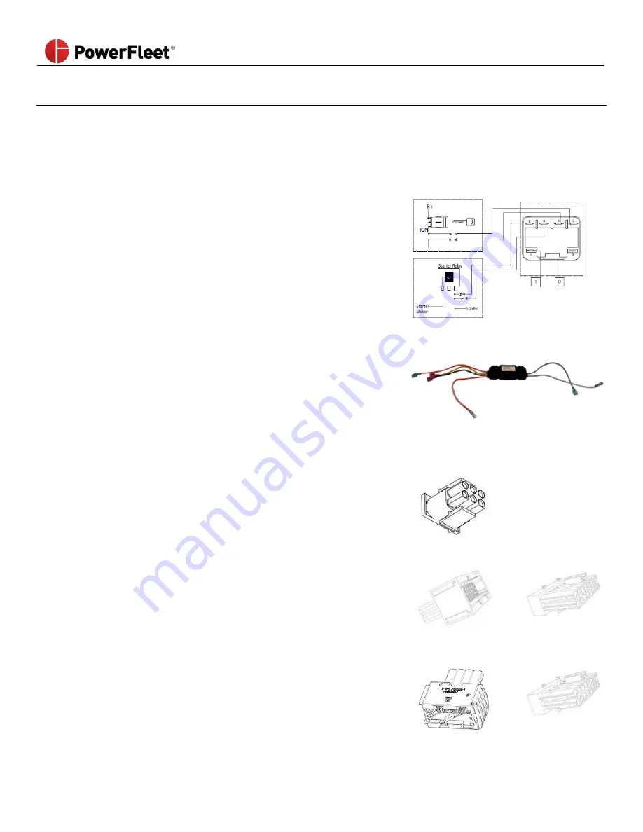
Hard-bypassing access control
You must open the vehicle and have access to the PowerFleet® relay circuit to complete this procedure.
Depending on the access control relay you are using, the connection points may differ:
For relays with embedded spade terminals:
a.
Remove any wires connected to the #2 and #4 positions on
the access control relay and connect those wires (#2 and #4)
to each other.
b.
Remove any wires connected to the #6 and #8 positions on
the access control relay and connect those wires (#6 and #8)
to each other.
For relays with orange and grey wire connections:
a.
Remove any wires connected to the orange wires of the
access control relay and connect those wires to each other.
b.
Remove any wires connected to the grey wires of the access
control relay and connect those wires to each other.
3
OEM custom vehicle harnesses only, perform the following:
iPort Connector:
a.
Disconnect the iPort cable harness from the vehicle
connector and disable the iPort feature on the Vehicle
Manager (for more information, contact your Vehicle
Manufacturer representative).
iPort
Connector
Still/Linde/Jungheinrich JPT Connector:
a.
Disconnect the JPT cable harness from the vehicle
connector.
b.
Connect the VMS bypass bridge to the
Still/ Linde/ Jungheinrich JPT connector.
Still/Linde/Jungheinrich
JPT connector
VMS Bypass
Bridge
VDI and P-Plug Connectors
a.
Disconnect the VDI cable harness from the vehicle
connector and disable the VDI feature on the Vehicle
Manager (for more information, contact your Vehicle
Manufacturer representative).
VDI Connector
P-Plug
Connector