


PowerFleet
®
VAC4 and VAC4S Hardware User’s Guide
085-00000700 Rev K
Page 24 of 103
VAC Synchronization
Wirelessly, using Intelligent RF (IRF)
When a successfully configured VAC comes within wireless coverage range of a Wireless Asset Manager (WAM), the VAC
will automatically synchronize its configuration with the PowerFleet Vision Pro software configuration. The first
synchronization may take 5 to 10 minutes, depending on the number of changes (added operators, groups, etc.) made in
Vision Pro software. Subsequent synchronizations may take from a few seconds to a minute.
Wirelessly, using Wi-Fi
When a successfully configured VAC (including Wi-
Fi profiles; see “Wi
-
Fi Configuration on the VAC”) comes within
wireless coverage range of a working and valid Access Point, the VAC will automatically synchronize its configuration
with the Vision Pro software. The first synchronization may take 5-10 minutes, depending on the number of changes
(added operators, groups, etc.) made in the Vision
Pro™
software. Subsequent synchronizations may take from a few
seconds to a minute.
Impact Sensor Configuration
There are 3 steps to achieving a functional impact management system once the impact sensor is properly physically
installed. Refer to the PowerFleet Installation Guide. Each step is automatic and designed to work out-of-the-box.
The
first step
is calibrating the impact sensor, which
relies on proper installation and mounting. The purpose
of the calibration is similar to resetting an empty scale to
zero pounds before weighing an object. A valid reference
point is needed. The calibration process is automatically
performed during the VAC Configuration process above.
Once that process is completed without errors, the
impact sensor has its initial calibration. The system then
automatically re-calibrates the sensor once per day
during periods of inactivity to make sure the environment
hasn’t changed (i.e. the
sensor came loose from the
mounting surface).
If a subsequent calibration attempt fails, a diagnostic
error is reported.
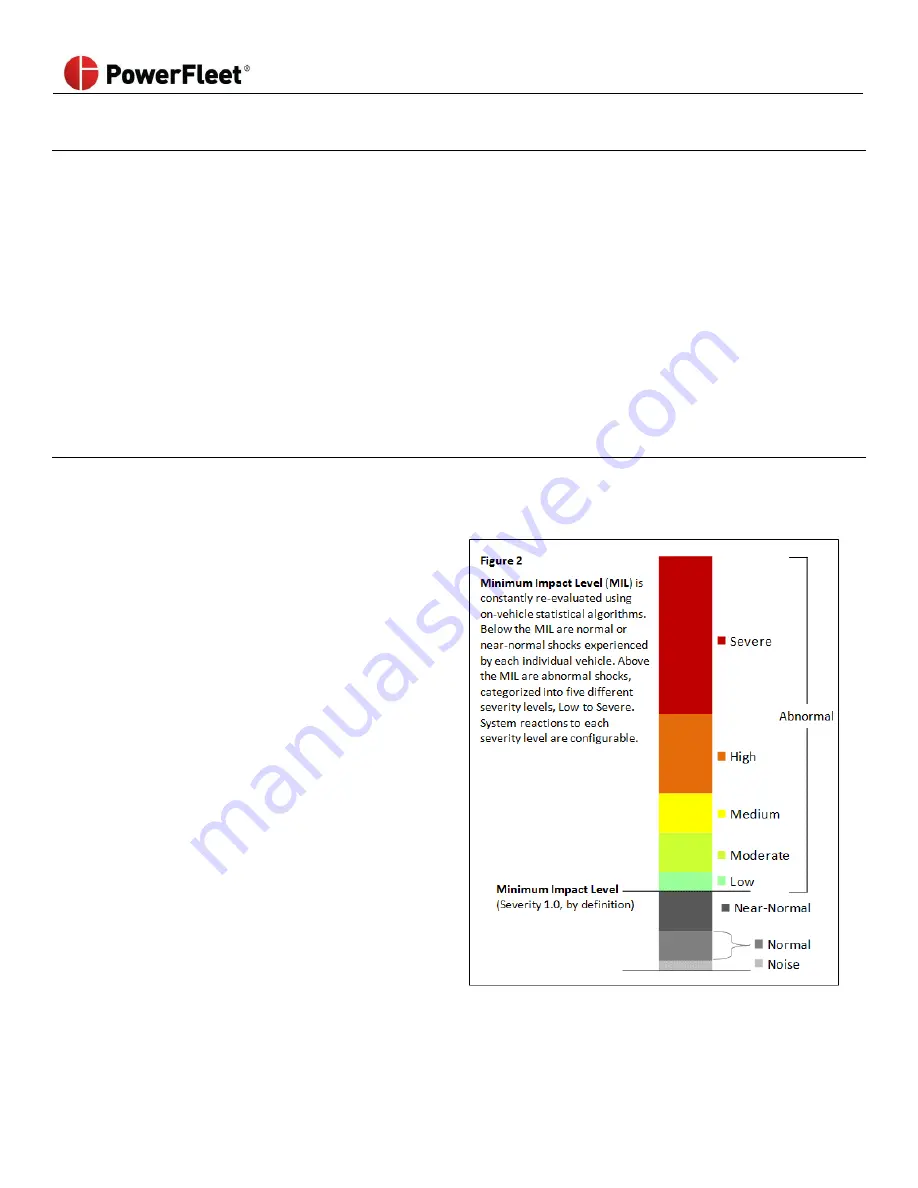
The
second step
is determining a valid Minimum Impact
Level (MIL) Threshold. The MIL quantifies the point
between “normal” and “abnormal” shock activity on each
individual vehicle, and forms the basis for defining the
relative severity of abnormal impacts. The MIL is an
automatically calculated point, based on continuous
evaluation of real-time impact data, which adjusts
automaticall
y to reflect the actual range of “normal”
shock activity on each vehicle as it changes over time
(due to different drivers, environments, tasks, etc.).
By definition, the MIL is assigned a Severity Level of 1.0, no matter how its calculated value fluctuates. Below this level,
shock activity is classified as Normal, Near-Normal, or simply Noise, and is not recorded in detail. Above the MIL, impacts