


PowerFleet
®
VAC4 and VAC4S Hardware User’s Guide
085-00000700 Rev K
Page 64 of 103
SECTION 6: WAM USE and TROUBLESHOOTING
Refer to the WAM Installation Guide (IRF or Cellular version) to perform initial WAM installation and testing.
WAM Use
Once installed, the WAM (including its integrated modem) automatically communicates with both VACs and the
PowerFleet Vision Pro system software. Normal operation does not require any further human interaction.
Note:
Wi-Fi deployments do not require WAMs, however they can be used as supplemental communication.
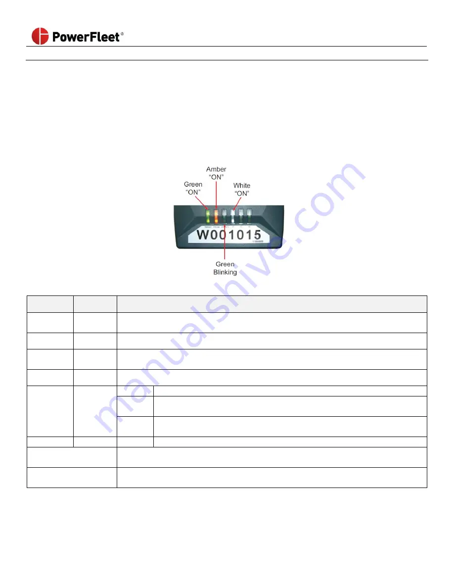
LEDs of Fully Operational WAMs and Cellular Modems (if applicable)
WAM LEDs Explained
LED
LED Color
Function
Pwr /
Slp
Green /
Yellow
System is running normally. Once installed, this LED should always be on, except during a
facility blackout. A yellow light means the unit is in sleep mode.
EthLink
Amber
Ethernet port is connected. This light should always be on.
EthActivity Green
Blinks when valid Ethernet packet is received or transmitted. Green light should be
blinking if the Ethernet port is active.
F1
White
On after boot-up. If flashing, then authorization is not transmitted.
F2
Blue
On
No connectivity to the host computer.
Blinking
WAM is sending data over the network to the host computer. Once installed,
this is expected behavior.
Off
Connection is fine, but WAM does not have data to send. (e.g. No vehicles
nearby and no diagnostic data to send).
F3
Red
Blinking
WAM is in remote control mode.
Process or
Running Indicator
Always through red LEDs blink sequentially if not running.
(Always happens when power is first applied to the WAM).
Process or Running but
Error Reported
LEDs blink from RED to WHITE
(i.e. Backwards sequentially) if error.