


PowerFleet
®
VAC4 and VAC4S Hardware User’s Guide
085-00000700 Rev K
Page 18 of 103
SECTION 2: CONFIGURING THE HARDWARE
VAC Configuration
A VAC equipped vehicle cannot be used by the Standard or Master operators until the VAC has been successfully
configured by a Maintenance operator for the BASIC configuration wizard. The VAC on-screen message and blinking red
LED is displayed. (
Note: instructions for testing the BLU wire connection prior to VAC configuration are in Section 5
).
Once the PowerFleet Enterprise vehicle hardware has been properly installed, the vehicle can only be accessed using the
yellow maintenance IDs, or a Maintenance level operator login. When a Maintenance operator logs in, they will be
required to follow a series of VAC screen display instructions displayed to verify the installation and configuration. This
process time is about 3 to 5 minutes and requires the operator to perform the following:
1.
Enter or confirm the Facility ID. This number is unique to the facility where your system is operating. For VACs in
your facility with the incorrect Facility ID, there will be no communication to the system infrastructure.
•
Your facility ID was communicated to the system coordinator with your software access credentials.
•
If you enter a zero on the facility ID screen, the IRF VACs will assign the facility ID of the first WAM it
communicates with (while on the facility ID screen).
•
If you do not know the facility ID, contact
PowerFleet’s
Support.
2.
Enter or confirm your license key (based on features purchased).
•
License key was communicated to the system coordinator with the assigned software access credentials.
•
If you do not know the facility ID, contact
PowerFleet’s
Support.
3.
Select vehicle type:
FR
Forklift Rider
OP
Order Picker
SE
Sweeper
TR
Turret Truck
FS
Forklift Stand-up
PC
Preconditioned Air
SR
Stacker Rider
TT
Tow Tractor
GP
Ground Power Unit
PR
Pallet Jack Rider
SW
Stacker Walkie
TV
Truck/ Van
JB
Jet Bridge
PW
Pallet Jack Walkie
TH
Other
ML
Man Lift
RT
Reach Truck
TL
Towbarless Tow
4.
Enter the vehicle label number. The numeric value is between 1 and 65534.
5.
Select a vehicle Engine Type (VDI CAN interface VACs skip steps 5-7 and drive tests):
Electric
Electric motor
Gas/IC
Internal combustion
iPort
iPort enabled Raymond electric
6.
Select what the Green and Yellow wires are connected to for access control:
On/Off Relay
Relay supplied with kit
Vehicle PWM Circuit
Connected to vehicle circuit with PWM
7.
For Electric vehicles, select the BLU wire input type (where the BLU wire was connected to):
V (Avg)
Voltage average mode
V (min/max)
Voltage minimum/maximum mode
8.
Follow the VAC Configuration Wizard’s
VAC screen display prompts for performing vehicle actions (i.e. start
vehicle, release brake, drive forward, drive in reverse, etc.)
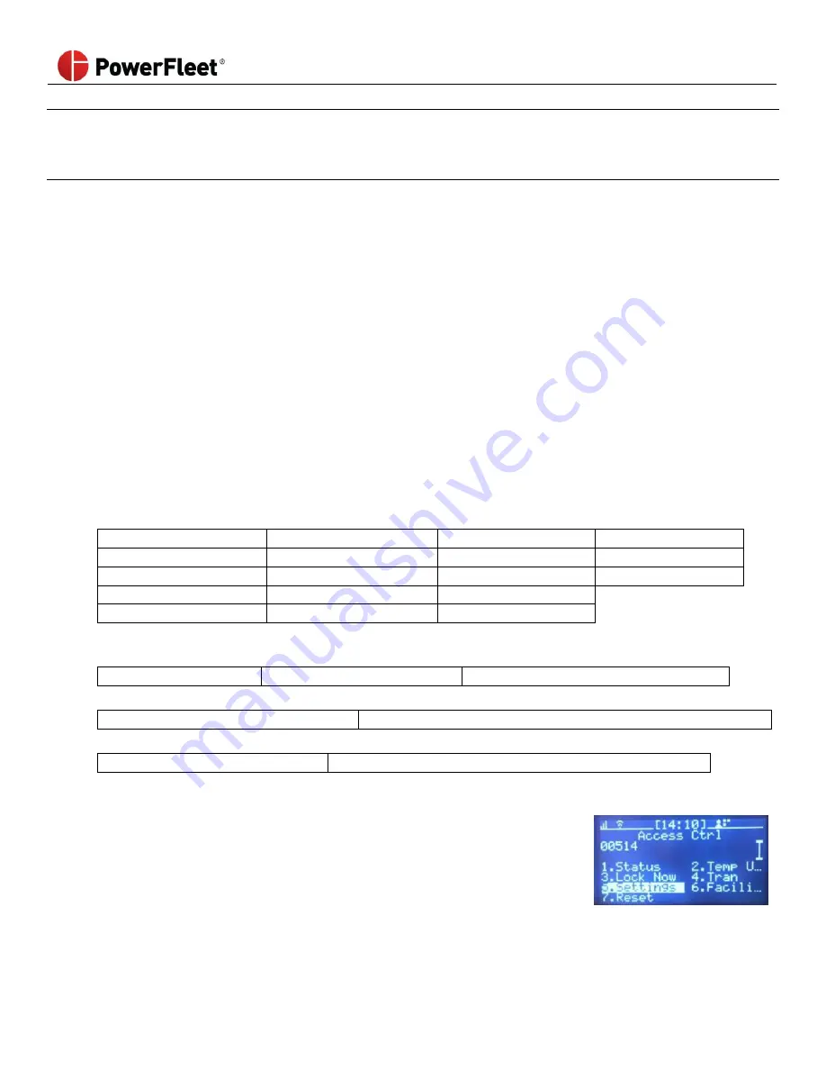
Once the VAC has been configured without
errors, the VAC is active in “Any ID”
mode and any hardware-compatible ID can access the vehicle. In Any ID mode, the
system will NOT lock out vehicles due to impacts, critical checklist responses, etc. If
you are unsure which mode the system is in, check the operator icon in the header
of the VAC screen when logged in or Maintenance operators can determine the
current VAC mode using the Access menu. (Any ID mode has the icon color inverted)
(See
‘ID Optional’ in Section 5
: Maintenance Operators for more details).
Note:
If the configuration fails and an error message is displayed, refer to Section 7: VAC Troubleshooting.