


PowerFleet
®
VAC4 and VAC4S Hardware User’s Guide
085-00000700 Rev K
Page 54 of 103
Understand and Manually Set “Motion” for Electric Vehicles
(Not applicable for JPT, P-Plug and VDI cable installations)
The VAC installation and configuration wizard is always used for establishing motion and idle thresholds on a vehicle. In
some cases, motion and idle values may need to be adjusted during troubleshooting. One reason may be that the vehicle
will not pass the initial configuration wizard. Another reason may be that motion diagnostic errors appear regularly.
The VAC determines the state of the vehicle (idle or motion) by configuring two ‘idle’ ranges based on voltage sampling
of the
“
BLU
” wire connection. The sampling methods (the numbers displayed) are different depending on the Vehicle
Type (e.g. Elec avg, Elec min/max). The two idle ranges will typically differ
when the “
BLU
” connection
voltage changes
between key-on and key-off while the motor is disengaged. In other scenarios, the two idle ranges may be identical.
1.
Log into the vehicle.
2.
On the first menu screen, select HARDWARE.
3.
Scroll down to the second page of the menu screen.
4.
On the “Hardware” sub
-menu, select MOTION.
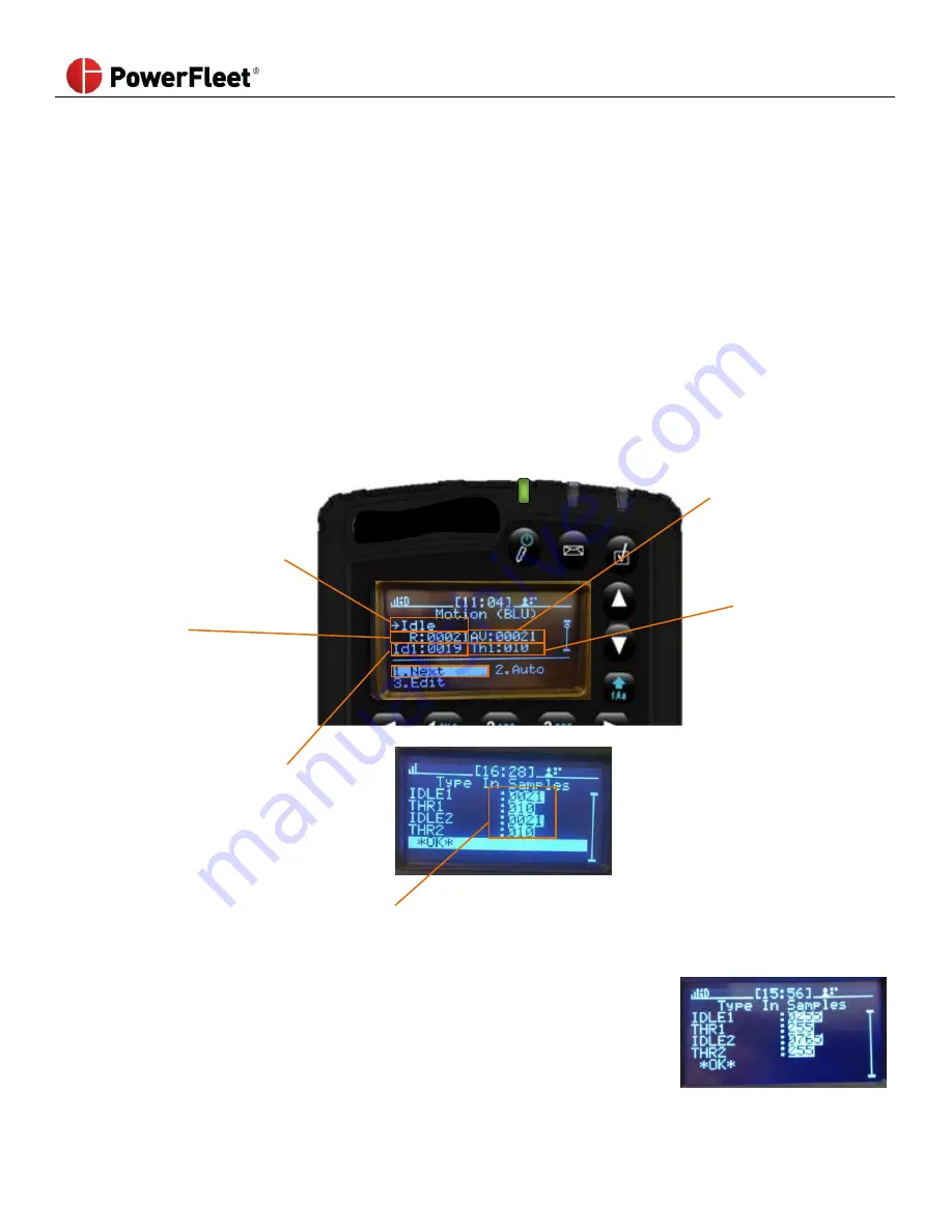
Idle
or
Motion
Current ‘motion’ state
of the vehicle.
MUST BE VALIDATED
VIA TEST DRIVE AFTER
CHANGING SETTINGS
AV
Current value
evaluated versus
idle ranges to
determine vehicle
state.
R
“Raw” value currently
being measured by
sensor
Th1
Threshold above
and below Id1
center point that
equals the ‘idle’
range.
Id1
Center point for first
‘idle’ setting range
.
Th2
Threshold above
and below Id1
center point that
equals the ‘idle’
range.
Id2
Center point for second
‘idle’ setting range
.
Select EDIT which opens a new screen where you can type in the required values between 0 and 1023 (center point)
and between 0 and 255 (range). This method is a last resort and would be used in a trial-and-error scenario with
assistance from PowerFleet Support.
IDLE1
Center point for 1st idle setting.
THR1
Range around (+/-
) the “IDLE1” setting that makes the idle threshold
.
IDLE2
Center point for 2nd idle setting.
THR2
Range around (+/-
) the “IDLE2” setting that makes the idle threshold
.
Pictured
example
Vehicle is idle when AV is between 0 and 510 (255 ± 255) or 510 and
1020 (765 ± 255).