

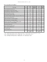


3-17
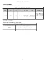
PFC-6030 • 5403595 • REV C-1 • 10/13
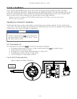
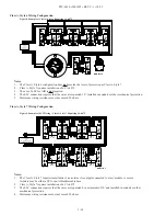
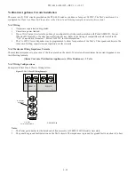
Dual Contact Module – 4 inch Mount (DCM-4)
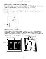
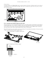
Refer to the figure shown below for a Class A DCM-4 wiring example.
Figure 15. DCM-4 with One Class A Circuit
S-
S+
SLC Loop
To Next Module
From FACP or Previous Module
Dual Contact Module
Model No. DCM-4
LED
Note: The resistance of external wiring shall be less that 100Ω.
The capacitance of external wiring shall be less than 1 micro farads.
JP1
Select Style 6
NO1
C1
Z1
NO2
C2
Z2
DWG #593-15
Note
: In this configuration, the DCM-4 operates as a single point Class A module.
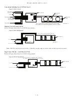
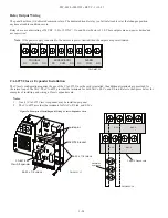
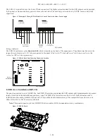
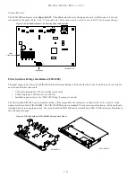
When configuring a Class B, the DCM-4 has two (2) addresses. If address No.1 is set, input circuit No.1 (NO1, C1) will be
addressed as No.1, and input circuit No.2 (NO2, C2) will automatically be addressed as No.2. Refer to
the
figure
below for an
example
of
wiring
a
Class
B
DCM-4.
Figure 16. DCM-4 with Two Class B Circuits
S-
S+
SLC Loop
To Next Module
From FACP or Previous Module
Dual Contact Module
Model No. DCM-4
LED
Note: The resistance of external wiring shall be less that 100Ω.
The capacitance of external wiring shall be less than 1 micro farads.
JP1
Select Style 4
NO1
C1
Z1
NO2
C2
Z2
Address #
Address #+1
DWG #593-16
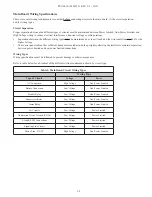
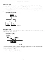
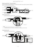
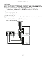
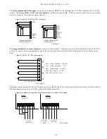
Twin Relay Module – 4 inch mount (TRM-4)
The TRM-4 has two (2) contacts that are active simultaneously when TRM-4 is in the active mode. Normal output is nonpower-
limited, unless the power supply connected to the TRM-4 is power-limited and the circuits are power-limited.
Figure 17. Example of TRM-4 Wiring
S-
S+
SLC Loop
To Next Module
From FACP or Previous Module
Twin Relay Module
Model No. TRM-4
LED
NO1
C1
NC1
NO2
C2
NC2
Contact Rating:
24VDC / 2.0A
125VAC / .5A
Normally Open 1
Common 1
Normally Closed 1
Normally Open 2
Common 2
Normally Closed 2
DWG. #593-17


