background image

- 20 -

TRANSP 9500 D/F/GB/NL (297)

GB

NL

F

D

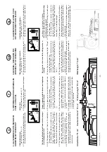
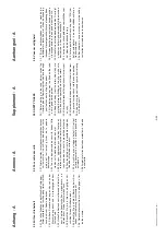
5.6 Travail avec une toupie

Consigne de s

é

curit

é

!

Vous devez 

ê

tre sur un sol plat et ferme

pour effectuer la modification de la position

travail en position transport.

Attention!

Observer la remarque au paragraphe 2.5.12!

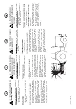
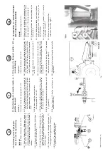
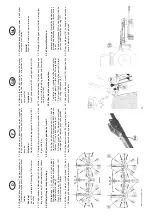
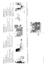
5.6.1 Mettre l'appareil en position travail.

(Voir paragraphe 5.5)

5.6.2 Retirer du bo

îtier central (1O) le cardan de la

toupie qui ne sera pas utilis

é

e.

5.6.3 L'enfiler sur l'embout (6O) placer sur le b

â

ti.

Attention !

Assurez-vous que l'attelage pivotant est libre

et que personne ne se trouve dans le p

é

rim

è

tre

de s

é

curit

é

.

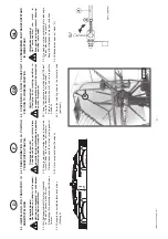
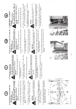
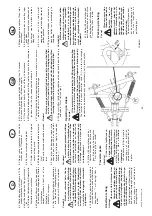
5.6.4 A l'aide du relevage hydraulique, relever les deux

toupies compl

è

tement et laisser les arr

ê

ts (11)

s'enclencher. (position E).

5.6.5 A l'aide de la goupille (11a) bloquer l'arr

ê

t (11) de

la toupie qui ne sera pas utilis

é

e.

5.6 Conversion to single rotor operation

(border areas)

Safety Precaution!

Changing from working position to

transport position is only to be carried out

on even, firm ground.

Important!

Please observe the notes in item 2.5.12!

5.6.1 Adjust the machine to working position (see item

5.5).

5.6.2 Pull off the drive shafts which are to be put out of

action at the central gear (10).

5.6.3 Push the drive shafts which have been removed

onto the rear profile peg (60) on the bearing frame.

Important!

Make sure that the swivel area is free and that

no one is standing in the danger area!

5.6.4 Lift out both rotors completely using the tractor

control appliance and lock both locking flaps (11)

into position (position E).

5.6.5 Fix into position the locking flaps which are to be

put out of action using the spring cotter (11a)

delivered.


5.6 WERKEN MET 1 ELEMENT.

(inhooien)

Veiligheidsaanwijzing!

Het omschakelen van werk- in

transportstand en omgekeerd, alleen op

een effen, vaste ondergrond uitvoeren.

Attentie!

Let op de aanwijzing onder 2.5.12!

5.6.1 Machine in werkstand brengen (zie 5.5).

5.6.2 Tussen-as van het element dat niet gebruikt

wordt, bij de hoofdaandrijving afkoppelen (10).

5.6.3 Afgekoppelde tussen-as op de achterste

geprofileerde houder (60) koppelen.

Attentie!

Overtuig u ervan dat er niemand in de

gevarenzone van de machine is!

5.6.4 Beide elementen in transportstand heffen en met

de beide grendels (11) vergrendelen (stand "E").

5.6.5 Grendel van het element dat buiten gebruik is met

de meegeleverde borgpen (11a) beveiligen.

5.6 Umstellung auf Einkreiselbetrieb

(Grenzr

ä

umen)

Sicherheitshinweis!

Das Umstellen von Arbeits- in Transport-

stellung und umgekehrt nur auf ebenem,

festem Boden durchf

ü

hren.

Achtung!

Beachten Sie die Hinweise in Punkt 2.5.12!

5.6.1

Ger

ä

t auf Arbeitsstellung bringen (siehe Pkt 5.5)

5.6.2  Gelenkwelle des Kreisels, welcher au

ß

er Betrieb

gesetzt werden soll, beim Mittelgetriebe (10) ab-

ziehen.

5.6.3 Abgezogene Gelenkwelle auf den hinteren

Profilzapfen (60) am Tragrahmen aufschieben.

Achtung!

Vergewissern, da

ß

 der Schwenkbereich frei

ist und sich niemand im Gefahrenbereich

befindet!

5.6.4  Beide Kreisel mit Schleppersteuerger

ä

t ganz

ausheben und beide Verriegelungsklappen (11)

einrasten lassen (Stellung E).

5.6.5 Verriegelungsklappe des Kreisels der au

ß

er Be-

trieb gesetzt wurde durch mitgelieferten

Federvorstecker (11a) fixieren.

Summary of Contents for EUROTOP 620 N

Page 1: ...PAGE 3 Nr 99 297 FR 809 0 Ihre Your Votre Masch Nr Fgst Ident Nr D F Operating instructions INSTRUCTIONS FOR PRODUCT DELIVERY Page 3 Nr 99 297 GB 809 0 GB TOP 620 N Type SK 297 01001 EUROTOP 620 N Ty...

Page 2: ...ations Confirmation is necessary to prove that the machine and operating manual have been handed over accordingly For this purpose document A is to be signed and sent to P ttinger document B remains w...

Page 3: ...auf festen Sitz berpr ft Auf richtige Zapfwellendrehzahl hingewiesen Anpassung an den Schlepper durchgef hrt Dreipunkteinstellung Gelenkwelle richtig abgel ngt Probelauf durchgef hrt und keine M ngel...

Page 4: ...disponibles Explications concernant l utilisation la prise en main et l entretien de la machine donn es selon le livret d entretien Contr le de la pression des pneumatiques Contr le du serrage des cro...

Page 5: ...ts checked re tightness Drive shaft cut to correct lenght Correct power take off speed indicated Fitting to tractor carried out to three point linkage Trial run carried out and no defects found Functi...

Page 6: ...ebruiker besproken en uitgelegd Bandenspanning gecontroleerd Wielbouten en moeren op vastzitten gecontroleerd Op het juiste toerental van de aftakas gewezen Aanspanning aan de trekker gecontroleerd en...

Page 7: ...ntage van extra uitrustingsdelen 20 21 Smeermiddelenvoorschrift 22 23 Smeerschema 24 Instructions d utilisation Table des mati res Page Plaque du constructeur Chargement correct 4 Donn es techniques O...

Page 8: ...teur d clare que les machines r pondent aux diff rentes exigences fondamentales de s curit et de sant CE Zeichen Das vom Hersteller anzubringende CE Zeichen dokumentiert nach au en hin die Konformit t...

Page 9: ...lt elke aansprakelijkheid van de fabrikant Voor het keren en harken van groenvoer ruwvoer en voordroogkuil Jeder dar ber hinausgehende Gebrauch gilt als nicht bestimmungsgem F r hieraus resultierende...

Page 10: ...flecteur d andain voir instruction de montage Cha ne pour limiter la descente Reproduction interdite Tous droits et modifications r serv s Les illustrations sont engagements pour la forme 1 Technical...

Page 11: ...any are listed in the Instructions for ancilliary appliances The traffic registration authority StVZO also stipulates that the ancilliary equipment must be equipped with rear reflectors warning signs...

Page 12: ...HET WEGZETTEN VAN DE MACHINE machine op de voorste en achterste steunpoten zetten 12 13 3 Attelage au tracteur 3 1 1 Recommandations pour la s curit voir Annexe A1 p 2 3 2 5 2 3 1 2 Avant la premi re...

Page 13: ...3 D verrouiller la b quille arri re 13 la replier vers le haut et la fixer avec l axe et la goupilles 13a 5 3 4 Brancher le flexible hydraulique au tracteur 5 3 5 Mettre la corde 14 dans la cabine du...

Page 14: ...soient l ext rieur les d monter gauche 15 comme droite 16 et les fixer sur le support 20 5 3 6 Swing left and right deflector hoops 6 inwards and secure with spring cotter 6a 5 3 7 Twist both of the...

Page 15: ...arr t 4 position G Rabattre le panneau B 5 3 12 Lever l appareil Attention aux hauteurs de transport prescrites 5 3 8 Open the isolating valve on the hydraulic tube 4 position A 5 3 9 Lift left and r...

Page 16: ...tre la corde 14 dans la cabine du tracteur 5 4 4 V rifier l enclenchement correct de chaque arr t 11 position E 5 4 5 Lever l appareil Attention aux hauteurs de transport prescrites 5 4 Conversion to...

Page 17: ...racteur r gler la hauteur de travail 75 cm de la machine voir sch ma Relever le panneau B et le fixer avec la goupille 5 5 2 Ouvrir le robinet d arr t Position A 5 5 VERANDEREN VAN TRANSPORTSTAND IN W...

Page 18: ...ette du distributeur ST du tracteur sur descente Les deux toupies descendent et l attelage pivotant se d verrouille 9 5 5 3 Switch the tractor control appliance to lift The two rotor hydraulic cylinde...

Page 19: ...ars 17 drive shafts in alignment Fix this position on the hoisting gear control lever 50 using the stopper 51 5 5 9 Using both of the hand cranks 18 adjust the tine contact of each rotor 5 5 6 Gedeeld...

Page 20: ...ing flaps 11 into position position E 5 6 5 Fix into position the locking flaps which are to be put out of action using the spring cotter 11a delivered 5 6 WERKEN MET 1 ELEMENT inhooien Veiligheidsaan...

Page 21: ...e harrow is effected finally using the tractor s control device ST When lowering the machine the swivel frame s locking device 9 is automatically raised 5 6 6 Andere element in werkstand brengen zie 5...

Page 22: ...rsnelling en aandrijftoerental en is afhankelijk van gewas en terreinomstandigheden 6 RECOMMANDATIONS GENERALES POUR LE TRAVAIL Safety hints see supplement A1 points 2 10 6 1 Arr ter la prise de force...

Page 23: ...uer la vitesse de rotation de la prise de force 6 9 Pour viter des dommages relever votre appareil pour franchir des obstacles importants telle que rigole travers e de chemin Prudence Les machines qui...

Page 24: ...sement la machine D crocher la machine l abri Prot ger les pi ces o la peinture est partie Graisser l aide du plan de graissage 7 Maintenance and servicing Safety hints see supplement A point 2 5 11 T...

Page 25: ...001 0 Lighting set kpl Pos 4 5 K type 1 278 25 001 0 Warning signs kpl 6 13 16 20 1 4 32 20 041 0 Rear lighting unit left f E type 1 4 32 20 046 00 Rear lighting unit left f K type 1 5 32 20 043 00 Re...

Page 26: ...26 WARTUNG 9500 D F GB NL 297 GB NL F D A n h a n g A n h a n g A n n e x e A n n e x e S u p p l e m e n t S u p p l e m e n t A a n h a n g s e l A a n h a n g s e l...

Page 27: ...297 SCHMIERPLAN 9900 D F GB NL CZ D 0 27 Schmierplan Plan de graissage Lubrication chart Smeerschema...

Page 28: ...h FETT 20 h FETT 20 h 1J SAE 90 0 75l FETT 20 h 10x Bj 1998 FETT 20 h FETT 20 h 1 J 1 x j hrlich 1 J 1 fois par an 1 J once a year 1 J 1 x jaarlijks 1 J 1 x ro n 20h alle 20 Betriebsstunden 20h Toute...

Page 29: ...von Ersatzteilen beachten 2 PREVENTION DES ACCIDENTS Attention Ce symbole dans ce manuel est plac cot de toutes les recommandations importantes relative votre s curit Observer les d une mani re sp ci...

Page 30: ...a Route de votre pays 2 5 5 La machine avec attelage pivotant N revient automatiquement en position centrale quand elle est relev e 2 5 6 Arr ter la rotation des tubes protecteur l aide de la cha nett...

Page 31: ...ier le bon enclenchement des arr ts 11 Fermer le robinet d arr t 8 position G 2 5 8 Pour les trajets sur route respectez les r gles du Code de la Route de votre pays 2 5 7 Before every trip Switch off...

Page 32: ...par le syndicat de la branche agricole en ce qui concerne la protection des accidents Mais ceci exclut toute responsabilit en cas d accident du a une utilisation incorrecte de la machine 2 5 9 De cir...

Page 33: ...D F GB NL Anhang Titelblatt _341 ANHANG ANNEXE SUPPLEMENT AANHANGSEL...

Page 34: ...bon march peut devenir tr s co teux Aussi exigez l originale marqu e du tr fle lors de votre achat Qualit t und Passgenauigkeit Betriebssicherheit Zuverl ssige Funktion H here Lebensdauer Wirtschaftli...

Page 35: ...zeer duur worden Let dus bij de aanschaf op het Original teken met het klaverblad Quality and precise fitting Operating safety Reliable operation Longer lasting Economy Guaranteed availability throug...

Page 36: ...und K92 4E ermitteln b Schrauben l sen wodurch die Reibscheiben entlastet werden Kupplung durchdrehen c Schrauben auf Ma L einstellen Kupplung ist wieder einsatzbereit GELENKWELLE Achtung Verwenden Si...

Page 37: ...92 4E b Desserrer les vis pour r duire la pression sur les garnitures de friction Faire tourner le limiteur c R gler les vis la dimension L Le limiteur friction est pr t fonctionner Cardan Attention N...

Page 38: ...and K92 4E b Loosen screws to release the pressure on the friction disk c Tighten set screws to dimension L Clutch is ready for use DRIVESHAFT Important Onlyusetheindicatedor accompanyingdriveshaft ot...

Page 39: ...tigd worden Blokkeerketting H nietvoor het ophangen van de kruiskoppelingsas benutten 1 Gebruiksinstructie voor een nokkenschakelkoppeling Denokkenschakelkoppeling is een beveiliging die het draaimome...

Page 40: ...jedoch mindestens 1 x j hrlich wechseln labla schraube herausnehmen das Alt l auslaufen lassen und ordnungs gem entsorgen Gear oils according to operating instructions however at least once a year Tak...

Page 41: ...RHENOX 34 GETRIEBE L B 85W 90 GETRIEBE L C 85W 140 OLNA 32 46 68 HYDRELF 46 68 PERFORMANCE 2 B SAE 30 8000 TOURS 20W 30 TRACTORELF ST 15W 30 TRANSELF TYP B 90 85W 140 TRANSELF EP 90 85W 140 EPEXA 2 R...

Page 42: ...st Abstand zwischen Schwerpunkt Frontanbauger t Frontballast und Mitte Vorderachse Radstand des Traktors Abstand zwischen Mitte Hinterachse und Mitte Unterlenkerkugel Abstand zwischen Mitte Unterlenke...

Page 43: ...ng des Traktors angegebene zul ssige Vorderachslast in die Tabelle ein 4 BERECHNUNG DES TATS CHLICHEN GESAMTGEWICHTES Gtat Wird mit dem Heckanbauger t GH die erforderliche Mindestballastierung Heck GH...

Page 44: ...ntre de gravit de l outil avant lestage avant et l axe de l essieu empattement du tracteur distance entre l axe de l essieu arri re et l axe des rotules des barres inf rieures distanceentrel axedesrot...

Page 45: ...r l essieu avant r elle calcul e et celle donn e dans la notice d instructions du tracteur sur le tableau 4 CALCUL DU POIDS TOTAL REEL Gtat Si avec l outil arri re GH il n est pas possible d atteindre...

Page 46: ...front ballast distance from centre of gravity for combinedfrontmountedimplement front ballast to front axle centre Tractor wheelbase distancefromrearaxlecentretocentreof lower link balls distance from...

Page 47: ...real front axle load and the permissible front axle load of the tractor into the table 4 CALCULATION OF THE REAL TOTAL WEIGHT Gtat Ifwiththerearmountedimplement GH therequiredminimumrearballasting GH...

Page 48: ...icht frontaanbouwmachine frontballast afstand tussen zwaartepunt frontaanbouwmachine frontballastenhet hart van de voor as afstand hart achteras tot hart hefkogel afstand hart achteras tot hart hefkog...

Page 49: ...dwerkelijke waarde en de in de gebruikershandleiding van de trekker aangegeven toegestane voor as belasting in de tabel in 4 Berekening van het daadwerkelijke totaalgewicht Gtat Als het minste ballast...

Page 50: ...benfalls Angabe der Firma und Anschrift des Herstellers erkl ren in alleiniger Verantwortung da das Produkt _________________________________________________________________________ Fabrikat Typ auf d...

Page 51: ...ant d clarons sous notre seule responsabilit que le produit _________________________________________________________________________ Marque mod le faisant l objet de la d claration est conforme aux p...

Page 52: ...s concerns authorized agents within the Common Market also state the company name and manufacturer declare in sole responsibility that the product _____________________________________________________...

Page 53: ...firma en het adres van de fabricant aangeven verklaren enig in verantwoording dat het product _________________________________________________________________________ fabricant type waarop deze verk...

Page 54: ...iterentwicklung arbeitet die P TTINGER Ges m b H st ndig an der Verbesserung ihrer Produkte nderungen gegen ber den Abbildungen und Be schreibungen dieser Betriebsanleitung m ssen wir uns darum vorbeh...

Page 55: ...sellschaft m b H A 4710 Grieskirchen Telefon 0043 0 72 48 600 0 Telefax 0043 0 72 48 600 511 e Mail landtechnik poettinger co at Internet http www poettinger co at GEBR P TTINGER GMBH St tzpunkt Nord...

Reviews: