PI E-727 User Manual Download Page 179

User Manual 

E727T0005, valid for E-727 

BRO, 2019-06-28 


Physik Instrumente (PI) GmbH & Co. KG, Auf der Roemerstrasse 1, 76228 Karlsruhe, Germany 

Page 179 / 240 

Phone +49 721 4846-0, Fax +49 721 4846-1019, Email 

[email protected]

, 

www.pi.ws


Exception: 


 Single-character commands are not followed by a termination character. The 
response to a single-character commands is followed by a termination character, 
however. 

The argument <AxisID> is used for the logical axes of the controller. Depending on the controller, 

an axis identifier can consist of up to 16 characters. All alphanumeric characters and the 

underscore are allowed. See "Axes, Channels, Functional Elements" (p. 22) for the identifiers 

supported by the E-727. 
Example 1: 
Axis 1 is to be moved to position 10.0. The unit depends on the controller (e. g. µm or mm). 
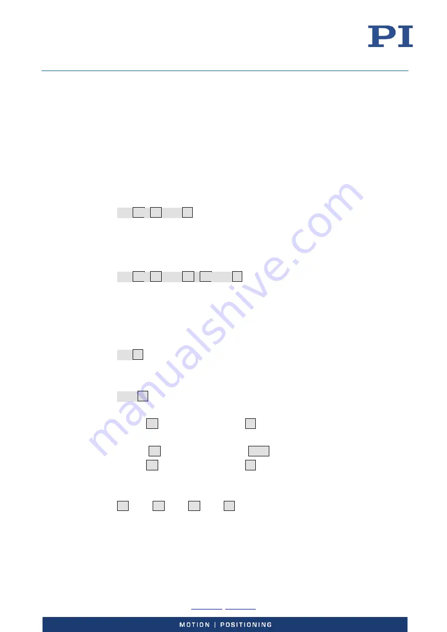
Send: 

MOV

SP

1

SP

10.0

LF


More than one command mnemonic per line is not allowed. Several groups of arguments following 

a command mnemonic are allowed. 
Example 2: 
Two axes which are connected to the same controller are to be moved: 
Send: 

MOV

SP

1

SP

17.3

SP

2

SP

2.05

LF


When a part of a command line cannot be executed, the line is not executed at all. 
When all arguments are optional and are omitted, the command is executed for all possible 

argument values. 
Example 3: 
All parameters in the volatile memory are to be reset. 
Send: 

RPA

LF


Example 4: 
The position of all axes is to be queried. 
Send: 

POS?

LF


The response syntax is as follows: 
 

[<Argument>[{

SP

<Argument>}]"="]<Value>

LF


With multi-line replies, the space preceding the termination character is omitted in the last line: 
 

{[<Argument>[{

SP

<Argument>}]"="]<Value>

SPLF


[<Argument>[{

SP

<Argument>}]"="]<Value>

LF

  for the last line! 

In the response, the arguments are listed in the same order as in the query command. 
Query command: 
 

CMD?

SP

<Arg3>

SP

<Arg1>

SP

<Arg2>

LF


Summary of Contents for E-727

Page 1: ...alid for E 727 BRO 2019 06 28 Physik Instrumente PI GmbH Co KG Auf der Roemerstrasse 1 76228 Karlsruhe Germany Phone 49 721 4846 0 Fax 49 721 4846 1019 Email info pi ws www pi ws E 727 Digital Multi C...

Page 2: ...on 13 Model Overview 13 Product View 14 Scope of Delivery 19 Accessories 19 Functional Principles 20 Block Diagrams 20 Axes Channels Functional Elements 22 Important Components of the Firmware 26 Inpu...

Page 3: ...unction Sensor Autoscaling 65 Data Recording 65 How to Use the Data Recorder 65 Data Recorder Related Commands and Parameters 67 Using Digital Input 68 Configuring Trigger Output 69 Overview of Trigge...

Page 4: ...Replacement of Tip Tilt Platforms with Differential Drive 132 Servo Controller Dynamic Tuning 134 Parameters to be Modified 134 General Notes on Servo Controller Dynamic Tuning 134 Adjusting the Notc...

Page 5: ...CAT Network 165 Connecting the EtherCAT Master 165 Configuring the EtherCAT Master 165 Scaling Position and Velocity Values 165 EtherCAT Communication 166 Communication State Machine 166 Communication...

Page 6: ...Table 217 Maximum Ratings 219 Ambient Conditions and Classifications 219 Operating Limits 220 System Requirements 222 Dimensions 223 Pin Assignment 225 E 727 for Capacitive Sensors Socket for Piezo S...

Page 7: ...I are affiliated with endorsed by or sponsored by National Instruments The following designations are registered company names trademarks or registered trademarks of their respective owners Linux MATL...

Page 8: ...ion NOTICE Dangerous situation If not avoided the dangerous situation will result in damage to the equipment Actions to take to avoid the situation Symbol Meaning Danger If not avoided the hazardous s...

Page 9: ...ual PI MATLAB Driver GCS 2 0 SM155E Software Manual PIMikroMove SM148E Software Manual Updating PI Software A000T0032 Technical Note PI Update Finder A000T0028 Technical Note Basic information on Ethe...

Page 10: ...of protected contents in the section User login for software download in the Release News Possibilities for the provision Link to a registration page for request of access data Direct display of user...

Page 11: ...epending on the model capacitive sensors or strain gauge sensors or piezoresistive sensors semiconductor strain gauge sensors must be used for closed loop operation PI stages intended for closed loop...

Page 12: ...to the protective earth conductor before starting it up again Organizational Measures User documentation user manual Technical Notes Always keep this user documentation available by the E 727 The late...

Page 13: ...o controller 3 axes 30 to 130 V piezoresistive sensors Sub D 37 socket 1 5 A peak output current E 727 3RDAP Digital multi channel piezo controller 3 axes 30 to 130 V piezoresistive sensors Sub D 37 s...

Page 14: ...oemerstrasse 1 76228 Karlsruhe Germany Page 14 240 Phone 49 721 4846 0 Fax 49 721 4846 1019 Email info pi ws www pi ws Product View Figure 1 Front panel of E 727 digital piezo controllers models E 727...

Page 15: ...cartridge fuse 5 x 20 mm changing the fuse see p 212 24 VDC M8 panel plug 4 pin p 232 Connection for the supply voltage To be used with the K050B0003 adapter included in the scope of delivery p 19 M4...

Page 16: ...3 4 OFL LED yellow Overflow indicator for the axes Continuously lit At least one of the axes is in overflow state Continuously off No axis is in overflow state Both OFL LEDs are flashing together with...

Page 17: ...to the PC SPI Display port Connection to SPI serial peripheral interface master Can be used for transferring position data from and to the E 727 with minimum latency and update rates as high as the s...

Page 18: ...green E 727 xxxF and xxxAF only EtherCAT communication state of the E 727 Off E 727 is in INIT state Blinking 2 5 Hz E 727 is in PRE OPERATIONAL state Single flash E 727 is in SAFE OPERATIONAL state...

Page 19: ...see p 230 Accessories Order number Description P 895 4LDS Adapter cable for four channels Sub D 37 m to 8 x Lemo 4 x piezo 4 x sensor 0 3 m For piezo stages with piezoresistive or strain gauge sensors...

Page 20: ...fo pi ws www pi ws Functional Principles Block Diagrams The following block diagrams show the basic structure of the E 727 For clear readability the block diagrams do not contain the additional analog...

Page 21: ...trumente PI GmbH Co KG Auf der Roemerstrasse 1 76228 Karlsruhe Germany Page 21 240 Phone 49 721 4846 0 Fax 49 721 4846 1019 Email info pi ws www pi ws Block diagram for models with EtherCAT interface...

Page 22: ...lled by an EtherCAT master E 727 xxxF and xxxAF only the EtherCAT master specifies target positions for the logical axes of the E 727 For further information see EtherCAT Interface S 164 Item Num ber...

Page 23: ...nsor Range Factor parameter ID 0x02000100 channel 4 can be configured as follows 1 Use with a piezoresistive or strain gauge sensor pins 6 24 25 2 Use with a PT1000 temperature sensor pins 1 20 E 727...

Page 24: ...stages p 225 or p 226 2 Position monitor of an axis output on pin 8 of the Analog I O socket p 228 5 Control signal for an external amplifier output on pin 8 of the Analog I O socket Further details s...

Page 25: ...4th wave generator is also present Wave tables 40 1 to 40 The wave tables contain the temporarily saved data a total of 262144 points for the waveforms that are output by the wave generators The value...

Page 26: ...arameters is determined by command levels The current command level can be changed with the CCL command This may require entering a password For more information see Parameters p 185 The values of som...

Page 27: ...igital conversion Digital processing filtering and linearization scaling Allocation of input signal channels to axes via the input matrix to calculate the axis positions from the input signals Figure...

Page 28: ...rrect system performance The basic form of the polynomials is as follows To make the system components easily replaceable sensor i e mechanics and electronics use separate polynomials The coefficients...

Page 29: ...rols 3 axes and has 3 channels for internal sensors and 4 additional analog input lines the last four input signal channels 7 6 5 4 3 2 1 37 36 35 34 33 32 31 27 26 25 24 23 22 21 17 16 15 14 13 12 11...

Page 30: ...on The control value for the motion of an axis can result from multiple sources see below Furthermore the feedback from multiple sensors can be used to maintain the axis position depending on the curr...

Page 31: ...CDA 3RDA 3SDA models The analog control input is enabled via parameter settings see How to work with the Analog Input p 85 for more information An offset value can be added to the analog input scaled...

Page 32: ...Karlsruhe Germany Page 32 240 Phone 49 721 4846 0 Fax 49 721 4846 1019 Email info pi ws www pi ws Open Loop Control all E 727 models Figure 9 Control sources for an axis in open loop operation Closed...

Page 33: ...721 4846 1019 Email info pi ws www pi ws Closed Loop Control when EtherCAT communication is running E 727 xxxF xxxAF only Figure 11 EtherCAT master controls an axis in closed loop operation Closed Lo...

Page 34: ...27 i e each parameter has a different value for each of the logical axes p1i Driving Factor of Piezo 1 parameter ID 0x09000000 p2i Driving Factor of Piezo 2 parameter ID 0x09000001 p3i Driving Factor...

Page 35: ...mand The slew rate limit for an axis is given by the Servo Loop Slew Rate parameter ID 0x07000200 Control Algorithms The control algorithm to be used in closed loop operation can be selected for each...

Page 36: ...ration 1 1 The PID algorithm can be configured with the following parameters Parameter Notes Servo Loop P Term ID 0x07000300 P constant for position control Must be 0 For further details see Servo Con...

Page 37: ...example If no input signal channel is selected the target signal is used as feedforward signal value of parameter 0x07030900 is zero The feedforward signal is fed in before the notch filters to avoid...

Page 38: ...f 1 deactivates the notch filter The notch rejection value determines the filter width of the notch filter i e it scales the damping done by the notch filter The greater the rejection value the wider...

Page 39: ...troller To read the ID chip data the controller must be power cycled or rebooted using the RBT command or the corresponding host software functions A piezo stage can be easily exchanged due to the fun...

Page 40: ...9 06 28 Physik Instrumente PI GmbH Co KG Auf der Roemerstrasse 1 76228 Karlsruhe Germany Page 40 240 Phone 49 721 4846 0 Fax 49 721 4846 1019 Email info pi ws www pi ws Overview of PC Software PI s sy...

Page 41: ...cquisition and process control must be ordered separately from National Instruments The E 727 software is a collection of virtual instrument drivers VI drivers for the E 727 controller In addition to...

Page 42: ...er To provide the Device Parameter Configuration window PIMikroMove requires the NI LabVIEW Run Time Engine see Performing the Initial Installation p 43 For users who want to perform simple automation...

Page 43: ...in the range of 100 kHz Keep in mind that low frequency signals may have harmonics in the range of 100 kHz If interfering signals in the range of 100 kHz cannot be avoided take particular care to ens...

Page 44: ...e InstallShield Wizard window The InstallShield Wizard interrupts the installation of the PC software for the E 727 until the installation of the NI LabVIEW Run Time Engine is started in the separate...

Page 45: ...p 43 2 Start the installation wizard by double clicking the PI_E 727 CD_Setup exe file in the installation directory main directory of the CD The InstallShield Wizard window for the installation of p...

Page 46: ...C software Prerequisite Active connection to the Internet If your PC uses a Windows operating system You have installed the PI Update Finder from th product CD p 43 You have the A000T0028 Technical No...

Page 47: ...directory with the unpacked files go to the linux subdirectory 11 Unpack the archive file in the linux directory by entering the command tar xvpf name of the archive file on the console 12 Read the ac...

Page 48: ...tandards for mounting the protective earth conductor Prerequisite You have read and understood the Safety precautions p 11 The E 727 is switched off via the Power switch Tools and accessories Suitable...

Page 49: ...n the E 727 in the case of malfunction or failure of the system If touch voltages exist touching the E 727 can result in serious injury or death from electric shock Connect the E 727 to a protective e...

Page 50: ...set to the axis travel range in rad e g 50000 rad s with S 334 For axis 3 the parameter value should be set to 100 100 V s When the E 727 is not used but is to remain switched on to ensure the tempera...

Page 51: ...nnected to pin 2 the signal level is HIGH internal pull up with 10 kohm resistor which means normal operation of the E 727 If the signal level on the Reset input becomes LOW the E 727 is rebooted Make...

Page 52: ...lternately lit and all other LEDs are off If no DHCP server is found the static IP address set with parameter ID 0x11000600 is used Phase 3 E 727 initializes parameters The Servo LEDs are alternately...

Page 53: ...e than one sensor Creating Backup Files for Controller Parameters INFORMATION The properties of the E 727 and the connected stage s are stored in the E 727 as parameter values Create a backup copy on...

Page 54: ...s on the Axes tab card During the test moves observe the position display for the axes in the Current Value Position fields and the current output voltage s for the piezo actuator s in the stage s in...

Page 55: ...the figure above the open loop value for axis 1 was increased to 30 by clicking the button three times step size value is 10 The current position approximately corresponds to the commanded open loop...

Page 56: ...IFC baud rate for RS 232 only For querying and setting the interface parameters it is recommended to use the Configure Interface window in PIMikroMove There you can comfortably read modify and save t...

Page 57: ...atile memory e g with WPA 100 while the current command level is 1 the obtained IP address will become the new default address of the E 727 After switching on or rebooting the E 727 The starting proce...

Page 58: ...are displayed and set in a suitable way on your PC The necessary steps depend on the operating system used If your operating system distinguishes between Internet protocol version 4 TCP IPv4 and versi...

Page 59: ...the PC to check the PC settings you can open the Internet Protocol TCP IP Properties window as described above To change the IP mask send IFS 100 IPMASK mask mask must be identical to the Subnet mask...

Page 60: ...2 Select E 727 in the field for controller selection 3 Select the TCP IP tab on the right side of the window All E 727 controllers in the same network are listed in the PI Controllers field 4 Click th...

Page 61: ...ollowing The procedure for other PC software programs PITerminal drivers for use with NI LabVIEW software is similar 1 Start PIMikroMove The Start up controller window opens with the Connect controlle...

Page 62: ...lar 1 Start PIMikroMove The Start up controller window opens with the Connect controller step If the Start up controller window does not automatically open select the Connections New menu item in the...

Page 63: ...nominal travel range Prerequisites for AutoZero LowVoltage HighVoltage LowVoltage is given by the value of the AutoZero Low Voltage parameter ID 0x07000a00 HighVoltage is given by the value of the Au...

Page 64: ...xes step of the Start up controller window execute the AutoZero procedure To re open the Start up controller window with the Start up axes step select the E 727 Start up axes menu item in the main win...

Page 65: ...has no ID chip The stage has piezoresistive or strain gauge sensors PI has informed you that the stage design is suitable for sensor autoscaling currently this can apply to customized stages only Obje...

Page 66: ...start up macro Irrespective of the DRT settings data recording is always triggered by the following four commands STE step response measurement IMP impulse response measurement WGO wave generator sta...

Page 67: ...a recorder tables in volatile memory DRC Data Source parameter ID 0x16000700 and DRC Record Option parameter ID 0x16000701 DRC Get Data Recorder Configuration Reads current data recorder settings DRL...

Page 68: ...0x16000300 1 System 1 INT Data Recorder Chan Number the available data recorder points are allocated in equal shares to the number of tables given by this parameter 0x16000700 1 Data recorder table 8...

Page 69: ...nt value and filters can be applied to the axis position to reduce false triggers caused by position noise See Example Position Distance Trigger Mode p 71 2 OnTarget the on target status of the axis i...

Page 70: ...rameters using SPA volatile memory or SEP non volatile memory Furthermore you can use WPA to copy the current values from volatile memory to non volatile memory where they become the power on defaults...

Page 71: ...s each starting with the TrigOutID declaration Command mnemonic Axis selection Trigger mode selection Step size setting CTO TrigOutID 2 Axis TrigOutID 3 0 TrigOutID 1 Stepsize Instead of using the CTO...

Page 72: ...tant The trigger high time is adjustable using the Position Distance Trigger High Time parameter ID 0x18000401 Switch to command level 1 with CCL to have write access to the parameters To set the para...

Page 73: ...1 The trigger pulse length is constant The trigger high time is adjustable using the Position Distance Trigger High Time parameter ID 0x18000401 The parameter value is given in seconds If the paramet...

Page 74: ...ger output depends on the value of the Pos Distance Trig Single Direction parameter ID 0x18000300 Default Trigger pulses will continue to be generated For further details see Filtering for reduction o...

Page 75: ...range via the StartThreshold The distance between the start position of the axis and the StartThreshold setting has to be at least 3 times larger than the noise of the axis position peak to peak value...

Page 76: ...the sensor position noise is greater than one fifth of the TriggerStep value set this can lead to unwanted generation of multiple trigger pulses at the same position in Position Distance trigger mode...

Page 77: ...ated whenever the position is within the range defined by the start stop thresholds Trigger output is independent of the current direction of motion i e continues when the motion direction is reversed...

Page 78: ...The Pos Distance Trig Filter Time parameter 0x18000301 specifies a time filter The time filter is used to delay the trigger deactivation when the axis position falls below the start threshold due to...

Page 79: ...Roemerstrasse 1 76228 Karlsruhe Germany Page 79 240 Phone 49 721 4846 0 Fax 49 721 4846 1019 Email info pi ws www pi ws Figure 24 Position Distance Trigger Mode with threshold settings without any fil...

Page 80: ...7000901 The on target status is true when the current position is inside the settling window and stays there for at least the settling time The settling window is centered around the target position T...

Page 81: ...ch is to be used for trigger output TrigOutID Axis CTOPam 2 TriggerMode CTOPam 3 MinThreshold CTOPam 5 MaxThreshold CTOPam 6 General notation of the CTO command for this mode in fact the command argum...

Page 82: ...PA or SEP see Configuring Trigger Output p 69 for a parameter list Example 1 Generate single trigger pulses synchronized with the wave generator in Generator Level Trigger mode Command String to Send...

Page 83: ...tion will take place as specified WGO 1 0 Stop output of Wave Generator 1 and hence also the trigger output Example Generator Pulse Trigger Mode With the Generator Pulse Trigger mode the trigger outpu...

Page 84: ...utOR trigger modes the signal states of multiple digital output lines are combined by a logical operation and the result is written to another trigger line A bit mapped mask selects the digital output...

Page 85: ...range of an analog input 5 V or 10 V can be configured via the value of the corresponding Sensor Range Factor parameter ID 0x02000100 You can use an analog input line as follows Connect an external se...

Page 86: ...or configuration of the analog input requires command level 1 Switch to command level 1 as follows In a terminal program Send CCL 1 advanced When prompted to enter a password in any PC software e g in...

Page 87: ...lues after the scaling as position values in m In addition the digital filter parameters can be adjusted See Digital processing p 27 for details How to adjust OFFSET and GAIN to map the analog input v...

Page 88: ...GAIN GAIN MaxScaledValue MinScaledValue MaxNormalizedValue MinNormalizedValue OFFSET MaxScaledValue GAIN MaxNormalizedValue The values of MinScaledValue and MaxScaledValue depend on the travel range o...

Page 89: ...0 1 4 NormalizedValue Send SPA 4 0x02000200 20 SPA 4 0x02000300 1 4 Example 3 Positions with positive sign shall correspond to positive input voltages and positions with negative sign shall correspond...

Page 90: ...t is enabled for an axis then it overwrites the values of all other control sources for that axis except those from the AutoZero procedure The AutoZero procedure has the highest priority i e it will o...

Page 91: ...PA 1 0x07000503 1 to change the coefficient in volatile memory In PIMikroMove this parameter is available in the Axis Definition 1 parameter group in the Device Parameter Configuration window If only...

Page 92: ...o axis 3 Send SPA 1 0x07000506 0 2 0x07000506 0 3 0x07000506 0 to exclude the analog input line from the axis position calculation Then send SPA 1 0x06000500 2 0x06000500 3 0x06000500 to check the RAM...

Page 93: ...ls Functional Elements p 22 See Parameters p 185 for more information regarding the controller parameters and their handling Parameter ID CCL for write access Item Type Concer ned Max No of Items Data...

Page 94: ...he Position Report Scaling parameter ID 0x07001005 and the Position Report Offset parameter ID 0x07001006 to suitable values for the appropriate axis For an example see p 95 5 Control signal for an ex...

Page 95: ...and save parameter values with the corresponding buttons and menu items in the Device Parameter Configuration window of PIMikroMove For further details see the description of the output signal channel...

Page 96: ...parameter ID 0x07000001 it is 20 m to 120 m in the example Furthermore the output range to be used is 10 V to 10 V The resulting parameter values for the axis position scaling are as follows Position...

Page 97: ...ut signal channel 4 to a suitable value Driving Factor of Piezo 4 parameter ID 0x09000003 in PIMikroMove available in the Axis Definition 3 parameter group in the Device Parameter Configuration window...

Page 98: ...is position is to be output output type 2 0x09000000 to 0x09000003 1 Logical Axis 3 FLOAT Driving Factor of Piezo 1 to Driving Factor of Piezo 4 give the output matrix 0x0A000003 1 Output Signal Chann...

Page 99: ...mmand parameter ID 0x13000004 The E 727 provides 262144 data points for waveform definition This memory space is temporarily allocated to the individual wave tables during the waveform definition Basi...

Page 100: ...rm points low is also the power on default This can be done with TWS or TWC Then use the TWS command to define the trigger actions high low level rising falling edge for selected output lines at selec...

Page 101: ...ut by a wave generator If you want to modify a waveform with WAV first stop any wave generator output from the associated wave table The frequency of the wave generator output depends among other fact...

Page 102: ...of output cycles WGC the wave offset WOS and the output trigger settings TWS can be modified while a wave generator is running When a wave generator finishes by running through a specified number of...

Page 103: ...he controller also support use of the wave generator Waveforms can be defined stored and displayed in and by the software in a more user friendly way than in a terminal using WAV and WGO If using the...

Page 104: ...nd defines a waveform segment which either replaces or is appended to the waveform in the specified wave table Sine Curves WAV command Comments Waveform Segment WAV 2 X SIN_P 2000 20 10 2000 0 1000 Wa...

Page 105: ...defined segment will be appended to the existing wave table contents symmetric curve WAV 3 X SIN_P 4000 20 0 4000 0 3100 WaveTableID 3 AppendWave X WaveType SIN_P SegLength 4000 Amp 20 Offset 0 WaveL...

Page 106: ...le are overwritten by the new segment waveform offset 10 Do not confuse with the wave generator output offset set with WOS symmetric curve WAV 4 X RAMP 2000 35 0 2000 499 300 1000 WaveTableID 4 Append...

Page 107: ...nded to the existing wave table contents asymmetric curve Single Scan Line Curves WAV command Comments Waveform Segment WAV 1 X LIN 1500 30 15 1500 0 370 WaveTableID 1 AppendWave X WaveType LIN SegLen...

Page 108: ...the duration of the wave generator output using the wave table rate Command String to Send Action Performed WAV 2 X SIN_P 2000 20 10 2000 0 1000 Define a sine waveform for Wave Table 2 the segment le...

Page 109: ...mation Example 1 Generate single trigger pulses synchronized with the wave generator in Generator Level Trigger mode Command String to Send Action Performed WAV 2 X SIN_P 2000 20 10 2000 0 1000 Define...

Page 110: ...t of Wave Generator 1 immediately synchronized by servo cycle Now the trigger output action will take place as specified WGO 1 0 Stop output of Wave Generator 1 and hence also the trigger output INFOR...

Page 111: ...e which is detected on this input line If IN2 is used The generator output starts with the first rising edge which is detected on this input line and it will be stopped when a falling edge is detected...

Page 112: ...e CTO command must be used to activate the Generator Trigger mode for the desired digital output line TWS Get Trigger Line Action At Waveform Point WAV Set Waveform Definition A waveform must be defin...

Page 113: ...3000109 from volatile memory and the current interpolation type 9 Get Wave Generator Status Gets the current activation status of the wave generator but not the start options use WGO instead See How t...

Page 114: ...ve generator output cycles DDL initialization The information gathered is written to DDL tables and can then be used to refine the control output signals Working Principle p 114 describes the DDL basi...

Page 115: ...e factors the scan position is not exactly proportional to time but exhibits dynamic non linearity For periodic motion it is possible to record the errors for an axis during one or more DDL initializa...

Page 116: ...info pi ws www pi ws With DDL after one initialization period the error for constant speed motion will be reduced by a factor of about 100 and the dynamic error by a factor between 20 and 90 Figure 3...

Page 117: ...Send SEP 1 0x0D000000 reads the value from nonvolatile memory 2 PI will provide you with the DDL license number 3 Switch to command level 1 using the CCL command Send CCL 1 advanced 4 Write the DDL l...

Page 118: ...ivated DDL related commands will not provoke an error when the DDL feature is deactivated The number of DDL tables can be queried using the TLT command The number of DDL tables present in the E 727 is...

Page 119: ...e DDL command How to use DDL for an axis As long as your application does not change you can use the current DDL table content without new initialization In this case start the wave generator with WGO...

Page 120: ...Recalculates the DDL processing parameters Time Delay Max ID 0x14000006 and Time Delay Min ID 0x14000007 required if the servo parameters have changed DTC Clear DDL Table Data It is recommended that t...

Page 121: ...sequences as macros The following functionalities make macros an important tool in many application areas Several macros can be saved at the same time Any macro can be defined as the start up macro T...

Page 122: ...ecution MAC FREE Gets the free memory space for macro recording unit number of characters MAC NSTART macroname uint String1 String2 Starts the given macro n times in succession n number of executions...

Page 123: ...ros tab in PIMikroMove There you can conveniently record start and manage controller macros Details are found in the PIMikroMove manual Recording a macro INFORMATION A maximum of 5 nesting levels are...

Page 124: ...n to create a tab for entering a new macro Do not enter the MAC BEG macroname command 2 Enter the commands to be included in the macroname macro line by line using the normal command syntax Macros can...

Page 125: ...n the positive direction and waits until the axis has reached the target position Macro 2 performs this task for the negative direction of motion Macro 3 calls up macro 1 and 2 Record the macros by se...

Page 126: ...bles The sequence of the values in the input must correspond to the numbering of the appropriate local variables starting with the value of the local variable 1 The individual values must be separated...

Page 127: ...END MOVWAI moves axis 1 to the target position which is given by the value of the local variable 1 and waits until the axis has reached the target position 4 Start the execution of the MOVLR macro by...

Page 128: ...ands Details on working with the Controller macros tab in PIMikroMove are found in the PIMikroMove manual Stop the macro execution with the 24 or STP commands If you want to check whether an error has...

Page 129: ...automatically switched on Furthermore the AutoZero procedure can be executed automatically according to the value of the Power Up AutoZero Enable parameter ID 0x07000802 0 AutoZero procedure is not au...

Page 130: ...e put in curly brackets If the variable name consists of a single character the curly brackets can be omitted Note that if the curly brackets are omitted with variable names consisting of multiple cha...

Page 131: ...he E 727 Afterwards the complete set of ID chip parameters will be overwritten on power on or reboot only if the Power Up Read ID Chip option is enabled By default this option is disabled to facilitat...

Page 132: ...Parameter Configuration and select the System Mechanics groups where you can enable the option When this is done for all input signal channels associated with the stage press the Write selected edit...

Page 133: ...ogram is used 1 Switch to command level 1 by sending CCL 1 advanced to have write access to the Voltage Offset of Amplifier parameter 2 Query the value of the Voltage Offset of Amplifier parameter for...

Page 134: ...term parameter ID 0x07000300 I term parameter ID 0x07000301 Normally the proper P term and I term settings are found by observing the response of the axis to an abrupt change of the control value step...

Page 135: ...requency 1 value is set in the Parameter Settings panel of the Piezo Dynamic Tuner window the Servo Loop I Term value can be adjusted automatically in accordance The adjustment depends on the selectio...

Page 136: ...dow in PIMikroMove In addition to the measurement described below you can create a Bode plot In the PIMikroMove main window open the Data Recorder window via the E 727 Show data recorder menu item At...

Page 137: ...s d Select if and how the Servo Loop I Term is to be adjusted automatically when Notch Frequency 1 is changed Automatic I Term calculation 5 Perform the frequency response measurement by clicking the...

Page 138: ...than one resonance peak peak 1 is always the one with the lowest frequency In the figure below cursor 1 is at the first resonance peak 372 31445 Hz and cursor 2 is at the second next higher resonance...

Page 139: ...measured a second resonance peak enter the frequency value of the second resonance peak in the Notch Frequency 2 field in Hz If the second notch filter is deactivated rejection value 1 change the rej...

Page 140: ...ead the General Notes on Servo Controller Dynamic Tuning p 134 2 Make sure the stage is mounted in exactly the same way as in the application The load on the stage is especially important 3 Make sure...

Page 141: ...oop Mode box to move the axis in a permanent loop The loop mode is useful if you want to do the adjustment of the servo control parameters during the motion The loop motion can be stopped at any time...

Page 142: ...and settling time of the axis based on the recorded step response measurement d Check the step response result and compare it with the examples shown in the figures below The rise rate of the step res...

Page 143: ...of the step response is satisfactory when there is minimum overshoot and the settling time is not too long as in the figure below No changes are required for the servo control parameters 7 Save or di...

Page 144: ...es as high as the servo frequency of the PI controller It is also possible to send and receive ASCII data so that the host has full access to the PI General Command Set GCS The following block diagram...

Page 145: ...ter ID 0x10000501 In this case the data can be read and written directly in axis units Scaling is only necessary if any integer data type is set Using the Used Range for Fast IF parameter ID 0x1000050...

Page 146: ...1 is used to transfer axis target position data closed loop operation or open loop control values open loop operation For the direction from PI controller to host DS1 is used to transfer the current a...

Page 147: ...4 axes Data Word 1 Data Word 2 Data Word N 4 Byte 4 Byte 4 Byte 4 Byte The 32 bit data words are send with the highest bit first and the lowest bit last The following table shows one 32 bit data word...

Page 148: ...y to generate an interrupt so that the receiver FIFO can be read out The E 727 will also set this control value when large data blocks are transferred or when the speed is high before the complete dat...

Page 149: ...st data packet transmission failed This bit is always set when an CRC error occurred regardless if data segment 2 of the data packet contained a data stream or not The bits of PID bit 4 through bit 7...

Page 150: ...sport Layer Flow Charts The following flow charts show the transfer of data streams via data segment 2 It is shown for sender and receiver side separately The flow charts do not show the transfer of t...

Page 151: ...r FIFO or when FIFO is full depends on implementation Writing of data to sender FIFO is not shown Note 2 To check if the connection is lost an error counter can be added When too many errors occur the...

Page 152: ...nual E727T0005 valid for E 727 BRO 2019 06 28 Physik Instrumente PI GmbH Co KG Auf der Roemerstrasse 1 76228 Karlsruhe Germany Page 152 240 Phone 49 721 4846 0 Fax 49 721 4846 1019 Email info pi ws ww...

Page 153: ...005 valid for E 727 BRO 2019 06 28 Physik Instrumente PI GmbH Co KG Auf der Roemerstrasse 1 76228 Karlsruhe Germany Page 153 240 Phone 49 721 4846 0 Fax 49 721 4846 1019 Email info pi ws www pi ws Rec...

Page 154: ...pending on the PI controller type or host implementation However the following procedure is recommended Save the received DataSegmen2 Byte1 DataSegmen2 Byte2 and CTR2 bits temporarily to a buffer Set...

Page 155: ...r example when the system has 4 axes and the host sends target position data for 3 axes than only axes 1 through 3 are permanently updated by the interface Axis 4 remains at its initial position When...

Page 156: ...Bit 0 0 SMC A4 SMC A3 SMC A2 SMC A1 Changing the SMC bit changes the servo mode of the addressed axis as follows A change from 0 to 1 switches the servo mode of the addressed axis on closed loop oper...

Page 157: ...l 0 1 TwoBytes 0 SToggle 1 1st packet PID ST CTR2 CNT1 DS2 Axis 1 CRC 16 0x10 0x61 0x56 0x53 B11 B12 B13 B14 BC1 BC2 DataCtrl 1 0 TwoBytes 1 SToggle 0 2nd packet PID ST CTR2 CNT1 DS2 Axis 1 CRC 16 0x1...

Page 158: ...ut Input DCLK Serial data clock from PI controller Input Output Packet Transmission Because the SPI interface has only one clock the data packet transmission of host and PI controller runs simultaneou...

Page 159: ...onized with the command interface The falling edge of the LDAT line latches the current position values of all axis into the output FIFO With the next response packet the position values will be sent...

Page 160: ...this reason higher data rates are possible with DCLK It is possible to run the interface without using the DCLK line But in this case the delays on the transmission lines and the driver and receiver c...

Page 161: ...line must be terminated with 100 ohm Timing Diagrams Note that the time values depend on controller type The time values listed below were measured at the connector of E 727 Symbol Description Min Ma...

Page 162: ...7 BRO 2019 06 28 Physik Instrumente PI GmbH Co KG Auf der Roemerstrasse 1 76228 Karlsruhe Germany Page 162 240 Phone 49 721 4846 0 Fax 49 721 4846 1019 Email info pi ws www pi ws SCLK and data input S...

Page 163: ...27T0005 valid for E 727 BRO 2019 06 28 Physik Instrumente PI GmbH Co KG Auf der Roemerstrasse 1 76228 Karlsruhe Germany Page 163 240 Phone 49 721 4846 0 Fax 49 721 4846 1019 Email info pi ws www pi ws...

Page 164: ...d by EtherCAT master EtherCAT communication state OPERATIONAL drive state Operation Enabled The table below gives an overview over the most important characteristics of control via EtherCAT master for...

Page 165: ...used See the documentation of your EtherCAT master for details For the integration of the E 727 into the EtherCAT network the XML file delivered by PI Physik_Instrumente_Drives xml must be saved on t...

Page 166: ...g factor numerator of the EtherCAT master You can read or adjust the FieldbusAxis Resolution parameter value via the TCP IP or USB interface only for details see Parameters p 185 Parameter changes mus...

Page 167: ...stop input update SI Stop input update stop mailbox communication OI Stop output update stop input update stop mailbox communication Communication Details with E 727 EtherCAT communication can be est...

Page 168: ...the Notch Filter s in Open Loop Operation p 136 and Checking and Optimizing the Servo Control Parameters p 140 Optimization must be done via the TCP IP or USB interface Cycle Time During control via...

Page 169: ...and status word p 172 Figure 39 Drive state machine details The individual drive state machines for the axes of the E 727 can have different states State of drive state machine Characteristics NOT RE...

Page 170: ...w target and set point values Target and set point values are ignored FAULT An error occured and the Fault reaction active state has been passed Drive function disabled All axes of the E 727 are in th...

Page 171: ...AT master bit 2 of the control word must always be set Commanding the drive state transitions with combinations of bits 0 1 2 3 and 7 Command Bit 7 Bit 3 Bit 2 Bit 1 Bit 0 Transition Fault reset Enabl...

Page 172: ...ed Quick stop Voltage enabled Fault Operation enabled Switched on Ready to switch on Not ready to switch on 0 x 0 0 0 0 0 Switch on disabled 1 x 0 0 0 0 0 Ready to switch on 0 1 1 0 0 0 1 Switched on...

Page 173: ...ides the code of the last error which occurred in the E 727 Possible error code with E 727 0x4310 Excess temperature drive The error code indicates that the amplifier output is switched off because th...

Page 174: ...homing 8 Halt 0 1 Homing mode active Stop axis with profile deceleration The status word p 172 shows the success of the homing procedure Homing successful Bit 12 is set Homing not successful Bit 13 i...

Page 175: ...72 Bit Name Value Desciption 10 Target reached 0 Halt 0 Target position not reached Halt 1 Axis decelerates 1 Halt 0 Target position reached Halt 1 Axis has velocity 0 12 Setpoint acknowledge 0 Previo...

Page 176: ...INFORMATION Bit 10 of the status word indicates if the target position is reached The value of bit 10 is influenced by two parameters of the E 727 settling window On Target Tolerance ID 0x07000900 and...

Page 177: ...calculated by the E 727 as the difference of target and actual position In CSP the new target position is given cyclically by the EtherCAT master Bit 10 of the status word is therefore used as status...

Page 178: ...one command line LF LineFeed ASCII char 10 is the default termination character character at the end of a command line SP Space ASCII char 32 indicates a space character Quotation marks indicate that...

Page 179: ...er e g m or mm Send MOVSP1SP10 0LF More than one command mnemonic per line is not allowed Several groups of arguments following a command mnemonic are allowed Example 2 Two axes which are connected to...

Page 180: ...5SPLF 1 0000 0000LF Limitations for GCS Commands More than one command mnemonic per line is not allowed The number of characters per line is limited to 256 byte 1 character 1 byte This means that the...

Page 181: ...nalog Input Offset ATZ ATZ AxisID LowValue Set Automatic Zero Point Calibration ATZ ATZ AxisID Get State Of Automatic Zero Point Calibration CCL CCL Level PSWD Set Command Level CCL CCL Get Command Le...

Page 182: ...LP Get List Of Available Commands HLT HLT AxisID Halt Motion Smoothly HPA HPA Get List Of Available Parameters HPV HPV Get Parameter Value Description IDN IDN Get Device Identification IFC IFC Interfa...

Page 183: ...e RTR RTR Get Record Table Rate SAI SAI ALL Get List Of Current Axis Identifiers SEP SEP Pswd ItemID PamID PamValue Set Nonvolatile Memory Parameters SEP SEP ItemID PamID Get Nonvolatile Memory Parame...

Page 184: ...L VEL AxisID Get Closed Loop Velocity VOL VOL OutputSignalID Get Voltage Of Output Signal Channel WAC WAC CMD OP Value Wait For Condition WAV WAV WaveTableID AppendWave WaveType WaveTypeParameters Set...

Page 185: ...n the ID chip of the stage They are loaded to the volatile and nonvolatile memory when the E 727 is switched on or rebooted You cannot overwrite the parameters in the ID chip this can only be done by...

Page 186: ...enter a password in any PC software e g in PIMikroMove Enter advanced On command levels 1 write access is only available to PI service personnel Contact the customer service department if there seem t...

Page 187: ...The following special commands only change the corresponding parameters in the volatile memory To make them the new default values the changed values must be written to the nonvolatile memory with the...

Page 188: ...er ID 0x07000200 WOS Adds an offset to the wave generator output For the parameter concerned see p 112 WOS Reads the current valid offset value WTR Gives the wave generator table rate For the paramete...

Page 189: ...s Channels Functional Elements p 19 and the information in E 727 3CDA E 727 3RDA E 727 3SDA Analog I O p 228 0x02000102 INT 1 Input signal channel Sensor Offset Factor ID chip Only present with E 727...

Page 190: ...Signal Channel Minimum Position Of Sensor 0x02001D00 INT 1 Input Signal Channel Validate Sensor Position Range 0x03000n00 FLOAT 2 Input signal channel Sensor Elec Correction 1 n Coefficients of the po...

Page 191: ...n 0x03001000 FLOAT 2 Input signal channel Sensor Offset Correction 1 Coefficients of a polynomial for compensation of sensor offset non linearity Only present with E 727 models for piezoresistive and...

Page 192: ...tal Filter Bandwidth 0x05000101 FLOAT 1 Input signal channel User Filter Param 1 Coefficients for the USER filter type For further details see Digital Processing p 27 0x05000102 FLOAT 1 Input signal c...

Page 193: ...sition from Sensor 6 0x07000506 FLOAT 1 Axis Position from Sensor 7 0x07000600 CHAR 1 Axis Axis Name ID chip 0x07000601 CHAR 1 Axis Axis Unit ID chip 0x07000800 INT 1 Axis Power Up Servo ON Enable For...

Page 194: ...xis Adv Piezo Ctrl Stage Damping 0x07020200 FLOAT 1 Axis Adv Piezo Ctrl Resonance 0x07020500 FLOAT 1 Axis Adv Piezo Ctrl Stage Substituation Time 0x07020a00 FLOAT 1 Axis Adv Piezo Ctrl I Term Relation...

Page 195: ...0 FLOAT 1 Axis Notch Bandwidth 1 0x08000301 FLOAT 1 Axis Notch Bandwidth 2 0x08000400 FLOAT 1 Axis Creep factor T1 sec 0x08000401 FLOAT 1 Axis Creep factor T2 sec 0x08000500 INT 1 Axis Enable Notch In...

Page 196: ...t Numerical Format 7 raw format used for driver DAC issues 0x0b000800 INT 1 Output signal channel Input Index To Feed Back Not relevant for E 727 0x0b000a00 FLOAT 2 Output signal channel Min Output Vo...

Page 197: ...license 0x0e000401 INT 3 System DDL license valid 0x0e000b00 INT 3 System Number of input channels 0x0e000b01 INT 3 System Number of output channels 0x0e000b02 INT 2 System Number of system axes 0x0e...

Page 198: ...for the digital trigger input as follows 0 OFF Filter is disabled Processing of the trigger input is done immediately 1 ON Filter is enabled to reduce the influence of noise at the trigger input line...

Page 199: ...t 1 of the SPI interface For details see Configuring the Usage of Received Data p 145 0x10000501 INT 1 System FastIF Data Type Selects the data type for the data sent via data segment 1 of the SPI int...

Page 200: ...y used lower limit for the data sent via data segment 1 of the SPI interface For further details see Configuring the Limits for Position Scaling p 145 0x10000505 FLOAT 3 Axis FastIF Used High Limit Cu...

Page 201: ...Axis FieldbusAxis Resolution Scaling factor for target and current values transmitted via EtherCAT interface For further details see EtherCAT Interface p 164 0x10000801 INT 3 Axis Fieldbus Set Point...

Page 202: ...000b INT 3 System Max DDL Points 0x16000000 INT 1 System Data Recorder Table Rate For details see Data Recording p 65 0x16000100 INT 3 System Max Number of Data Recorder Channels 0x16000200 INT 3 Syst...

Page 203: ...igger Mode on p 71 0x18000301 FLOAT 1 Digital Output Line Pos Distance Trig Filter Time 0x18000302 FLOAT 1 Digital Output Line Pos Distance Trig Filter Level 0x18000400 INT 1 Digital Output Line Pos D...

Page 204: ...ss 0xffff0013 CHAR 2 Firmware Unit firmware device type 0xffff0014 INT 2 Firmware Unit hardware revision 0xffff0015 INT 2 Firmware Unit firmware dest addr 0xffff0016 INT 2 Firmware Unit firmware confi...

Page 205: ...f the E 727 via the included adapter 3 Connect the E 727 to the PC via USB interface USB type B 4 Switch on the E 727 a Connect the power cord of the wide range input power supply to the power socket...

Page 206: ...r Roemerstrasse 1 76228 Karlsruhe Germany Page 206 240 Phone 49 721 4846 0 Fax 49 721 4846 1019 Email info pi ws www pi ws 8 Click Connect The Connect window will open 9 Select the PI USB tab When the...

Page 207: ...Email info pi ws www pi ws The Connect window will be closed In the Select PI controller window now information on the connected E 727 should be displayed as shown below 10 Click Next Weiter means Nex...

Page 208: ...208 240 Phone 49 721 4846 0 Fax 49 721 4846 1019 Email info pi ws www pi ws A selection window opens 12 Select the directory where the file is located do not select the file and click OK The selection...

Page 209: ...7 BRO 2019 06 28 Physik Instrumente PI GmbH Co KG Auf der Roemerstrasse 1 76228 Karlsruhe Germany Page 209 240 Phone 49 721 4846 0 Fax 49 721 4846 1019 Email info pi ws www pi ws The window changes to...

Page 210: ...ws www pi ws 14 Click Start updating to start the firmware update The update progress will be displayed in the window see below Do not turn off the E 727 while the firmware update is in progress When...

Page 211: ...Updating the firmware p 205 Case 2 The PI Firmware Update Wizard ends with an error message and the E 727 does not reboot automatically Follow the procedure described for case 1 Case 3 After reboot o...

Page 212: ...Wait a minute to be sure that any residual voltage has dissipated 3 Clean the E 727 case surface with a cloth lightly dampened with a mild cleanser or disinfectant Changing the Fuse The E 727 is equip...

Page 213: ...ue Make sure that your network administrator has not set the network to forbid unknown devices like the E 727 to log on Note that if the controller is already connected to your or another host PC via...

Page 214: ...ds or in the Device Parameter Configuration window of PIMikroMove Incorrect command or incorrect syntax Send the ERR command and check the error code this returns Make sure that the used motion comman...

Page 215: ...is oscillating or positions inaccurately Possible Causes Solution The load was changed Unsuitable settings of the notch filter and the servo control parameters of the E 727 can cause the stage to osci...

Page 216: ...or written to the nonvolatile memory of the E 727 the servo mode is temporarily switched off This may lead to faulty control or large position errors Observe the following when you use the commands S...

Page 217: ...4x 4 Processor DSP 32 64 bit floating point 375 MHz Sampling rate servo control 20 kHz Sampling rate sensor 100 kHz Sensor E 727 Servo characteristics P I two notch filters Optional Advanced Piezo Con...

Page 218: ...rrent position Fieldbus EtherCAT CoE CANopen over EtherCAT Interfaces E 727 xxx E 727 xxxF E 727 xxxP E 727 xxxA E 727 xxxAF E 727 xxxAP Piezo sensor connection E 727 xCxx D Sub 25W3 f E 727 xSxx E 72...

Page 219: ...ivation of the voltage output at 72 C Alert threshold at 66 C Mass 2 4 to 2 6 kg 3 3 kg Fuse 1 x T3 15 AH 5 x 20 mm 1 x T4 AH 5 x 20 mm Max power consumption 80 W 84 W Max power consumption without lo...

Page 220: ...limit graphs in the figure below Note that the operating limits of a given piezo amplifier depends on the amplifier power the amplifier design and of course the capacitance of the piezo actuator The...

Page 221: ...mente PI GmbH Co KG Auf der Roemerstrasse 1 76228 Karlsruhe Germany Page 221 240 Phone 49 721 4846 0 Fax 49 721 4846 1019 Email info pi ws www pi ws Figure 40 E 727 xxx E 727 xxxA operating limits wit...

Page 222: ...he E 727 PC with Windows Windows 7 8 and 10 32 bit 64 bit or Linux operating system and at least 30 MB free memory Communication interface and corresponding cable Free COM port on the PC via RS 232 nu...

Page 223: ...KG Auf der Roemerstrasse 1 76228 Karlsruhe Germany Page 223 240 Phone 49 721 4846 0 Fax 49 721 4846 1019 Email info pi ws www pi ws Dimensions Dimensions in millimeters Decimal places are separated b...

Page 224: ...19 06 28 Physik Instrumente PI GmbH Co KG Auf der Roemerstrasse 1 76228 Karlsruhe Germany Page 224 240 Phone 49 721 4846 0 Fax 49 721 4846 1019 Email info pi ws www pi ws Figure 43 Dimensions of E 727...

Page 225: ...ut Index parameter ID 0x0A000004 determines the output signal channel whose control value is to be output Output on pin 8 of the Analog I O socket If a total of four piezo actuators are present in the...

Page 226: ...t 1 pin 8 on the Analog I O socket The use of output signal channel 4 can be configured via the value of the Select Output Type parameter ID 0x0A000003 as follows 1 Output voltage for a piezo actuator...

Page 227: ...max 5 V When nothing is connected to a digital input the signal level is high due to an internal pull up with 10 kohm resistor Digital In 4 pin 2 can be configured as reset input using the Reboot On D...

Page 228: ...lements p 22 INFORMATION When using an analog input of the E 727 both the corresponding Analog In and Analog In line must be wired Connect a differential signal analog analog GND as follows Customer D...

Page 229: ...e 10 V Analog outputs pins 8 14 7 15 Min 10 V at 5 mA output current Resolution DAC 20 bit Sensor Monitor lines 1 2 3 pins 14 7 15 The raw signals of the sensors 1 2 and 3 which are fed into the E 727...

Page 230: ...27 IO3x cable D Sub 15 m to open end L1 1 m 10 cm L2 6 cm 1 cm D Sub 15 m Signal Wire pair Color 1 GND Pair 1 brown 9 Analog In 1 Pair 2 green 2 Analog In 1 Pair 2 yellow 10 Analog In 2 Pair 3 grey 3...

Page 231: ...r cable is available as accessory p 19 The cable splits the input and output lines of the Analog I O socket p 228 up into 8 BNC connectors Figure 45 E 727 IO8 adapter cable D Sub 15 m to 8 x BNC L 0 4...

Page 232: ...info pi ws www pi ws RS 232 RS 232 D Sub 9 m Pin Function 1 nc 2 RXD receive data 3 TXD send data 4 nc 5 DGND ground 6 nc 7 RTS Hardware handshake output 8 CTS Hardware handshake input 9 nc Power Supp...

Page 233: ...me Direction 20 N C 19 LDAT Input 18 LDAT Input 17 CS Input 16 GND 15 CS Input 14 GND 13 GND 12 SCLK Input 11 GND 10 SCLK Input 9 MOSI Input 8 GND 7 MOSI Input 6 MISO Output 5 GND 4 MISO Output 3 DCLK...

Page 234: ...or make videos of your system that can be sent to our customer service department if requested The latest versions of the user manuals are available for download p 10 on our website Old Equipment Dis...

Page 235: ...0 Fax 49 721 4846 1019 Email info pi ws www pi ws EU Declaration of Conformity For the E 727 an EU Declaration of Conformity has been issued in accordance with the following European directives Low Vo...

Page 236: ...Product code RO 0x00000001 1 UNINT32 1018 03 Revision number RO 0 0 UNINT32 1018 04 Serial number RO UNINT32 Mappings Rx 1600 00 RxPDO CSP RO 3 1600 01 Controlword RO 0x6040 00 16 1600 02 Modes of op...

Page 237: ...Statusword RO 0x6041 00 16 1A00 02 Modes of operation display RO 0x6061 00 8 1A00 03 Position actual value RO 0x6064 00 32 1A00 04 Following error actual value RO 0x60F4 00 32 1A01 00 TxPDO PP RO 3 1...

Page 238: ...12 00 Sync Manage r2 PDO assignment RW P S 4 1C12 01 SubIndex 001 RW P S 0x1600 5632 1C12 02 SubIndex 002 RW P S 0x1610 5648 1C12 03 SubIndex 003 RW P S 0x1620 5664 1C12 04 SubIndex 004 RW P S 0 0 For...

Page 239: ...usword RO 0x0000 0 UINT16 6860 Modes of operation RW 0 0 INT8 6861 Modes of operation display RO 0 0 INT8 6864 Position actual value RO 0 0 INT32 687A Target position RW 0 0 INT32 687B 00 Position ran...

Page 240: ...0 INT32 707B 00 Position range limit RO 2 UINT8 707B 01 Min position range limit RW min axis limit INT32 707B 02 Max position range limit RW max axis limit INT32 707D 00 Software position limit RO 2...

Reviews: