


VARI
❋
LITE
®
- VL500™ L
UMINAIRE
S
ERVICE
M
ANUAL
5 0
21-May-2009
0 2 .9 6 8 5 .0 0 1 0 A
Main Control PCB/Fan Assembly Replacement
Parts:
21.9685.0731
1 EA
ASSY, VL500 MAIN CONTROL PCB/FAN
Tools:
•
1/4" Hex Nutdriver
•
#2 Phillips Screwdriver
WARNING:
Remove power from luminaire before performing maintenance.
To remove and replace main control PCB/fan assembly:
Step
1. Remove power from luminaire.
Step
2. Remove display-side yoke arm cover by removing four 6-32x3/8" PTB screws.
Step
3. Remove Display PCB as described in,
“Display PCB Replacement” on page 49
.
Step
4. At Main Control PCB/Fan Assembly, disconnect the following wiring connections:
a.
Pan/Tilt wiring harness
b. Head motor wiring harness
c.
3-position connector (Dimmer communications - VL500D and VL500 80V
models only)
d. 10-position AMP connector (Display Communications)
e.
4-position connector (DMX communications)*
CAUTION:
*This connector is similar to the connector for the LVS Fan/Temperature
Switch connector used on the Display PCB. It is imperative that you do not confuse the two.
f.
3-position connector (24V DC)
g. 5-position connector (Ballast communications - VL500A models only)
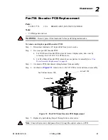
Step
5. Remove two 6-32x3/8" PPZ screws (one has a ground wire terminal attached).
Step
6. Remove four 1/4" hex (13/16" long) standoffs as indicated in
Figure 24
.
Summary of Contents for Vari-Lite VL500
Page 1: ......
Page 13: ...SAFETY NOTICE JAPANESE 02 9685 0010 A 21 May 2009 xiii ...
Page 14: ...VARI LITE VL500 LUMINAIRE SERVICE MANUAL xiv 21 May 2009 02 9685 0010 A ...
Page 34: ...VARI LITE VL500 LUMINAIRE SERVICE MANUAL 16 21 May 2009 02 9685 0010 A Notes ...
Page 118: ...VARI LITE VL500 LUMINAIRE SERVICE MANUAL 100 21 May 2009 02 9685 0010 A Notes ...
Page 168: ...VARI LITE VL500 LUMINAIRE SERVICE MANUAL 150 21 May 2009 02 9685 0010 A Notes ...
Page 212: ...VARI LITE VL500 LUMINAIRE SERVICE MANUAL 194 21 May 2009 02 9685 0010 A Notes ...
Page 218: ...VARI LITE VL500 LUMINAIRE SERVICE MANUAL 200 21 May 2009 02 9685 0010 A Notes ...
Page 219: ......