


I
LLUSTRATED
P
ARTS
B
REAKDOWN
:
3
0 2 . 9 6 8 5 . 0 0 1 0 A
21-May-2009
137
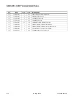
VL500 Pan/Tilt Motor Assembly (continued)
Figure 3-43: VL500 Pan/Tilt Motor Assembly
6
(x2)
Note
: Vari-Lite recommends that this assembly be replaced as a complete assembly. Although you can replace only the motor, the pulley (Item 2) is bonded
to the motor shaft during assembly and cannot be removed intact. If you order a replacement motor (Item 4), also order the pulley (Item 2). Contact Vari-Lite
Customer Service for installation information.
2
Drive Pulley Installation:
Step
1.
Apply one drop of Loctite
603 to motor shaft.
Step
2.
Install drive pulley on motor
shaft using twisting motion
to insure coverage of shaft
with loctite.
Step
3.
Do not allow Loctite to drip
into motor bearing.
Step
4.
Set pulley height as shown
above.
Step
5.
Apply Loctite 242 to pulley
set screws. Insure set
screws are aligned and
tightened on flat sides of
motor shaft.
Drive Pulley Detail & Installation
0.090" from Pulley to Motor
Tape goes under this
Note location of
board between standoffs.
codewheel with
respect to sensor
Pan & Tilt Motor Cross Section
8
(x2)
9
5
(x4)
7
(x4)
1
4
3
2
See Detail A
Detail A
2a
2b
2a
2a
Summary of Contents for Vari-Lite VL500
Page 1: ......
Page 13: ...SAFETY NOTICE JAPANESE 02 9685 0010 A 21 May 2009 xiii ...
Page 14: ...VARI LITE VL500 LUMINAIRE SERVICE MANUAL xiv 21 May 2009 02 9685 0010 A ...
Page 34: ...VARI LITE VL500 LUMINAIRE SERVICE MANUAL 16 21 May 2009 02 9685 0010 A Notes ...
Page 118: ...VARI LITE VL500 LUMINAIRE SERVICE MANUAL 100 21 May 2009 02 9685 0010 A Notes ...
Page 168: ...VARI LITE VL500 LUMINAIRE SERVICE MANUAL 150 21 May 2009 02 9685 0010 A Notes ...
Page 212: ...VARI LITE VL500 LUMINAIRE SERVICE MANUAL 194 21 May 2009 02 9685 0010 A Notes ...
Page 218: ...VARI LITE VL500 LUMINAIRE SERVICE MANUAL 200 21 May 2009 02 9685 0010 A Notes ...
Page 219: ......