2014-
02
52
IC-KP-B17-AIDA1
Commands
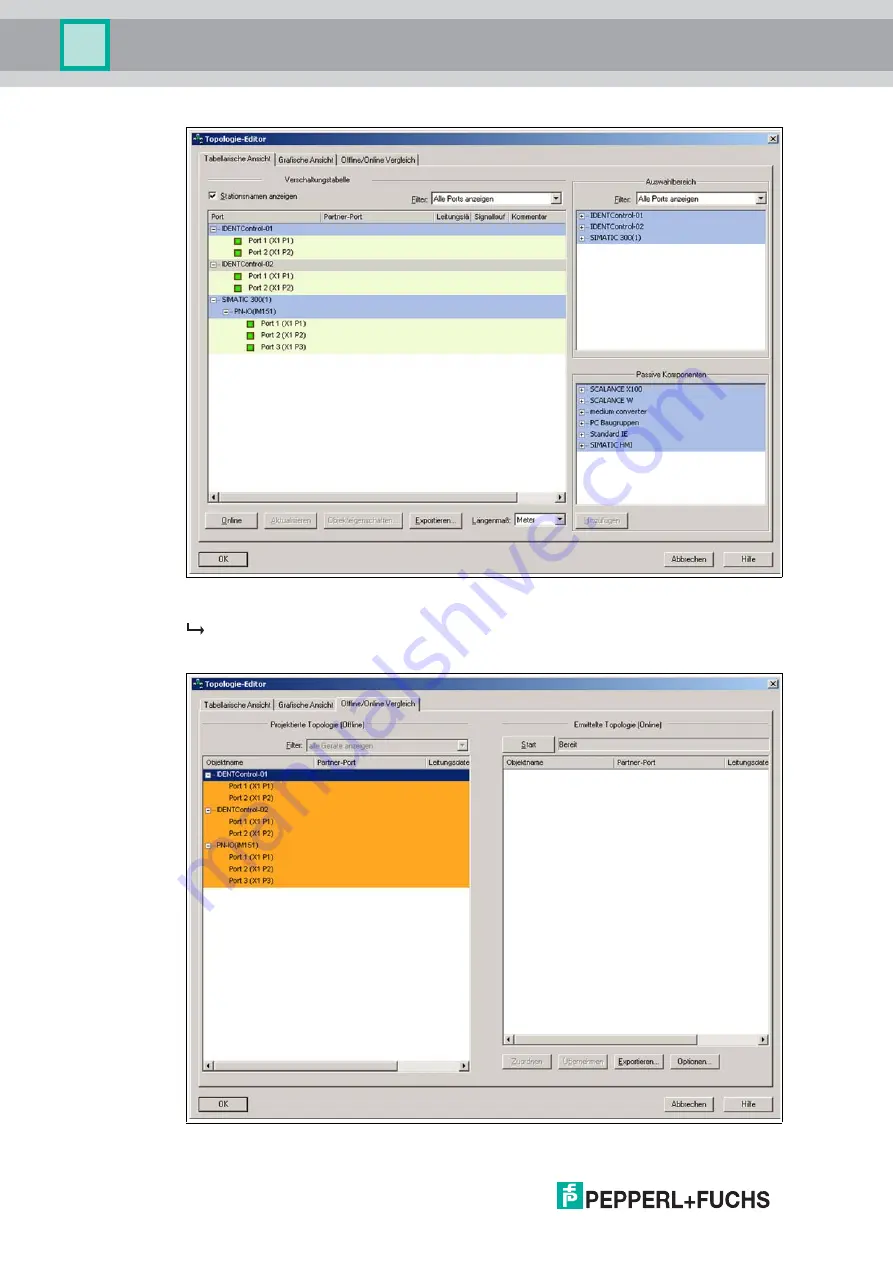
Figure 7.4
Table view
The interconnection table lists 3 devices.
3. Open the offline/online comparison by clicking the
Offline/online comparison
tab.
Figure 7.5
Page 1: ...IC KP B17 AIDA1 IDENTControl interface with Ethernet interface FACTORY AUTOMATION MANUAL...
Page 2: ...rms of Delivery for Products and Services of the Electrical Indus try published by the Central Association of the Electrical Industry Zentralverband Elektrotechnik und Elektroindustrie ZVEI e V in its...
Page 3: ...4 2 Device characteristics 11 4 3 Product Family 11 4 3 1 R W heads 11 4 3 2 Read Only Tags Read Write Tags 11 4 3 3 Handhelds 12 4 4 Displays and Controls 13 4 5 Interfaces and connections 14 4 6 Del...
Page 4: ...6 5 1 Using the identification system without a DHCP server 24 6 5 2 Using the identification system with a DHCP server 24 7 Commands 25 7 1 Data Exchange 25 7 2 Communication via TCP IP 26 7 2 1 Gen...
Page 5: ...ion via PROFINET 46 7 5 2 Overview of characteristics of the integrated PROFINET IO device 47 7 5 3 Project planning using device description GSDML 47 7 5 4 GSDML file and example project in the inter...
Page 6: ...03 10 2 Troubleshooting 104 11 ASCII table 105 12 Appendix A 106 12 1 Example 1 106 12 2 Example 2 110 13 Appendix B 120 13 1 Object model 120 13 1 1 Identity object 01h 120 13 1 2 Assembly object 04h...
Page 7: ...ce helps you to exploit the full functionality of the device avoids errors and related malfunctions avoids costs by disruptions and any repairs increases the effectiveness and efficiency of your plant...
Page 8: ...roducts were developed and manufactured under observance of the applicable European standards and guidelines The product manufacturer Pepperl Fuchs GmbH 68307 Mannheim has a certified quality assuranc...
Page 9: ...d exclude the manufacturer from any liability If serious faults occur stop using the device Secure the device against inadvertent operation In the event of repairs return the device to your local Pepp...
Page 10: ...ur components are made from metal either in part or in whole Figure 3 1 read head IDENTControl Danger Electric shock The metallic enclosure components must be connected to protective ground to protect...
Page 11: ...e controlling fieldbus is integrated into the enclosure and all connections are implemented as plugs This enables simple installation and quick correct replacement in case of device failure The consis...
Page 12: ...ode and a maximum 2 KB of programmable memory Data carrier 868 MHz UHF Data carriers in this frequency range can be passive as well as active with battery and use a specially shaped rod antenna as the...
Page 13: ...n has been established LED flashes green as soon as a signal has been sent to the IDENTControl via the Flashing PROFINET function or if there is an internal data overflow Link1 Link2 Connection to the...
Page 14: ...2 3 4 5 1 5 3 2 4 PE 1 2 3 4 5 signal Protection earth socket at housing read write head trigger sensor trigger switch voltage supply TD TD RD not used not used RD not used not used Ethernet 1 24 V 2...
Page 15: ...r that complies with the AIDA directive Figure 4 4 Connector Assignment Accessories Designation Field attachable connector for power supply ICZ AIDA1 MSTB MSTB connecting cable to M12 connector ICZ AI...
Page 16: ...Faraday cage Interference is caught in the shield and safely diverted via the ground connections The cable shielding is used to discharge electromagnetic interference When shielding a cable you must...
Page 17: ...gger sensors to the sockets on the top of the enclosure using M12 connectors For details of compatible read write heads see chapter 4 3 1 and of compatible connecting cables see chapter 4 7 1 5 4 3 Ca...
Page 18: ...ed lock washer 3 Crimp connector 4 Lock screw 1 2 4 3 Caution The network socket is connected galvanically to the grounded housing The Ethernet IP specification does NOT require the use of Ethernet ca...
Page 19: ...ne types The device can be operated in 10 Base T or 100 Base TX networks The maximum total line length is 100 m in both cases and only shielded network cables from category 5 or above can be used Refe...
Page 20: ...used Nature of access to the communication objects of the read write head Nature of the commands to the read write head Structure of the user program If you are planning larger projects or gaining ba...
Page 21: ...he device prior to commissioning A device that has not been configured or configured incorrectly may lead to faults in the plant Parameters Default setting Value range General Multiplex mode Off On of...
Page 22: ...rsion Channel No IPH1 IPH2 IPH3 IPH4 EnhancedRead Fixcode IPH1 IPH2 IPH3 IPH4 Channel X IPH1 IPH2 IPH3 IPH4 EnhancedRead 1 Word IPH1 IPH2 IPH3 IPH4 Channel X IPH1 IPH2 IPH3 IPH4 Triggermode IPH1 IPH2...
Page 23: ...dard Gateway IPH1 IPH2 IPH3 IPH4 Display MAC Adresse IPH1 IPH2 IPH3 IPH4 DHCP off IPH1 IPH2 IPH3 IPH4 IP XXX XXX XXX XXX IPH1 IPH2 IPH3 IPH4 SM XXX XXX XXX XXX IPH1 IPH2 IPH3 IPH4 SG XXX XXX XXX XXX I...
Page 24: ...via the display See chapter 8 2 6 5 2 Using the identification system in conjunction with a DHCP server In this case the parameters of a DHCP server are assigned to the identification system However...
Page 25: ...of parameters and the data relating to the command The confirmation consists of the telegram length TCP IP and MODBUS TCP IP only the echo of the command code the echo of the ident channel the status...
Page 26: ...P IP level before data can be exchanged From this point onwards commands can be sent from the client to the IC KP B17 AIDA1 device Command Confirmation Byte 0 Telegram length high byte N 1 div 256 Byt...
Page 27: ...Byte 4 Status Byte 5 Reply counter Byte 6 Read data Byte N Read data Note The toggle bit is not required for TCP IP 00 06 04 02 30 33 hexadecimal format 00 06 Telegram length 6 bytes 04 Command code C...
Page 28: ...it 0 06 Status 6 hardware error 02 Reply counter 00 06 10 22 00 00 00 06 Telegram length 6 bytes 10 Command code SR 22 Word number 2 Channel 1 toggle bit 0 00 00 Word address 0000 00 06 10 22 FF 01 00...
Page 29: ...ead write multiple registers Each channel is assigned a separate register area so that different controllers can each adopt a R W head Only one master has write permissions for each register area The...
Page 30: ...idual channel The following three register groups are assigned to each channel 1 Group 1 Output register device ID 1 2 Group 2 FIFO input register device ID 1 3 Group 3 FIFO monitor register device ID...
Page 31: ...communication between the controlling master and the identification system Channel 0 IDENTControl Channel 1 Channel 2 Channel 3 Channel 4 Group 1 Group 2 Group 3 0 122 0 124 0 124 3 2 3 2 1000 1122 3...
Page 32: ...f the identification telegram Use 0 K Reserved Reserved Deletion bit LSB 1 K Byte 0 Telegram length high byte N 1 div 256 Byte 1 Telegram length low byte N 1 mod 256 2 K Byte 2 Command code Byte 3 Res...
Page 33: ...element A master can therefore read data from the memory only once A protocolling master addresses the device using device ID 2 The protocolling master only has read permissions for the third group 7...
Page 34: ...ing example the tag type IPC03 is set to channel 2 and then a read command is executed The following prerequisites must be fulfilled One type IPH XX read head is connected to channel 2 The IP address...
Page 35: ...h change tag command Low byte Byte 3 Reserved Channel Toggle bit 00h No channel specification required 2003d High byte Byte 4 Data carrier type High byte 30h IPC03 Low byte Byte 5 Data carrier type Lo...
Page 36: ...must be fulfilled The example of the write multiple registers was executed successfully First step The MODBUS master parameters must be configured Second step A read holding registers MODBUS command m...
Page 37: ...ange tag command Low byte Byte 3 Reserved Channel Toggle bit 04h 4 corresponds to channel 2 Channel number shifted 1 bit to the left 2003d High byte Byte 4 Status 00h 00h command executed meaning of t...
Page 38: ...ng 2002d High byte Byte 2 Command code 19h enhanced read command Low byte Byte 3 Word number Channel Toggle bit 04h Word count 0 4 corresponds to channel 2 Channel number shifted 1 bit to the left 200...
Page 39: ...st four telegram bytes change The toggle bit can be used for this In this way the controller can transfer a register set several times during a cyclic data exchange without issuing a second identifica...
Page 40: ...nds that the device recognizes There is an important difference between these commands and commands used for TCP IP and MODBUS protocols Ethernet IP commands do not contain parameters for the command...
Page 41: ...e to process the data in the same memory area Channel 1 Channel 2 Channel 3 Channel 4 Channel IDENTControl Class 64h Instance 06 d Attributes 1 41 Class 65h Instance 06d Attributes 1 41 Input command...
Page 42: ...mplicit communication and so there are 13 possible combinations These combinations can be selected either via the device display the attribute 100 from instance 0 of the assembly object or by specifyi...
Page 43: ...m overwriting one another Sepa rated mode 104d 154d 8 8 8 8 32 32 105d 155d 12 12 12 12 48 48 106d 156d 32 32 32 32 128 128 107d 157d 60 60 60 60 240 240 108d 158d 8 8 8 8 8 40 40 109d 159d 12 12 12 1...
Page 44: ...the data hold time should not be much longer than necessary for the following reasons 1 The reaction time of the device will increase if several responses arrive in quick succes sion 2 The maximum pos...
Page 45: ...dAddr high byte N14 10 Write data DW 1 if not used please set to 0 N14 11 Write data DW 1 if not used please set to 0 N14 12 WordNum T command N14 13 WordAddr low byte WordAddr high byte N14 14 Write...
Page 46: ...liar IO view of PROFIBUS DP is used where the usable data of the field devices is cyclically transferred to the controller process image PROFINET IO is a device model consisting of slots and channels...
Page 47: ...of the field devices The peripheral input addresses incorporate the received data The user program evaluates and processes this data The user program generates the peripheral output values and sends...
Page 48: ...are identified in the network by their name and MAC address Names are assigned using the configuration tool Device creator Select a unique name for the IO device object in the programming and then ass...
Page 49: ...logy is stored in the Physical Device PDEV of the IDENTControl device Using the example of the Step7 software from Siemens you see an engineering tool that offers you options for topology detection us...
Page 50: ...IC KP B17 AIDA1 Commands Figure 7 2 HW Konfig Siemens Step7 Opening the topology editor 1 Open the topology editor by right clicking the Ethernet connection and then clicking the PROFINET IO Topology...
Page 51: ...IC KP B17 AIDA1 Commands 2014 02 51 Figure 7 3 Opening the topology editor 2 The topology editor opens...
Page 52: ...IC KP B17 AIDA1 Commands Figure 7 4 Table view The interconnection table lists 3 devices 3 Open the offline online comparison by clicking the Offline online comparison tab Figure 7 5 Offline online c...
Page 53: ...the Start button above the right hand window to identify the actual topology The detected topology online is shown in the right hand window 5 Confirm the detected topology by accepting the ports To d...
Page 54: ...ata includes information regarding the device within the system for example the installation location and installation date Maintenance data is initially stored in the device during installation this...
Page 55: ...field to FFh The reply counter value increases by 1 The status is displayed after the control interface executes the commands The toggle bit of the response is the same as the toggle bit of the comma...
Page 56: ...Byte 1 Telegram length low byte Byte 2 Command code Byte 3 Channel Toggle bit 0 Byte 4 Parameter Byte 5 Parameter Byte 6 Data to be written Byte N Data to be written Byte 0 Telegram length high byte...
Page 57: ...n the following pages System commands Standard read write commands Read only code Read data Write data Command code Command description Abbre viation 4d 04h See change tag CT on page 59 CT 2d 02h See...
Page 58: ...ite configuration SC on page 79 SC 102d 66h See enhanced buffered write configuration EC on page 80 EC Command code Command description Abbre viation 31d 1Fh Single write read only code SX 36d 24h Enh...
Page 59: ...RP 191d BFh See write param WP on page 94 WP Byte Contents Bit no 7 6 5 4 3 2 1 0 Byte 01 Telegram length high byte 0 0 0 0 0 0 0 0 Byte 11 Telegram length low byte 0 0 0 0 0 1 1 0 Byte 2 Command code...
Page 60: ...Tag it HF I Standard Texas Instruments Read write read only code 32 8 13 56 MHz 3 3 IQC332 FRAM MB89R118 Fujitsu Read write read only code 2k 8 13 56 MHz 3 4 IQC34 FRAM MB89R119 Fujitsu Read write rea...
Page 61: ...mber of 8 byte blocks here max 7 and must be an even number 3 Read write tags IQC40 IQC43 can only be used in combination with a IQH2 read write head WordNum specifies the number of 16 byte blocks and...
Page 62: ...0 0 1 0 Byte 3 Reserved Channel Toggle bit 0 0 0 0 Channel T 1 This byte is only used with the TCP IP and MODBUS TCP IP protocol Byte Contents Bit no 7 6 5 4 3 2 1 0 Byte 01 Telegram length high byte...
Page 63: ...o 7 6 5 4 3 2 1 0 Byte 01 Telegram length high byte 0 0 0 0 0 0 0 0 Byte 11 Telegram length low byte 0 0 0 0 0 1 0 1 Byte 2 Command code 17h 0 0 0 1 0 1 1 1 Byte 3 Reserved Ident channel Toggle bit Ch...
Page 64: ...0 0 0 0 Byte 11 Telegram length low byte 0 0 0 0 0 1 0 0 Byte 2 Command code 16h 0 0 0 1 0 1 1 0 Byte 3 Reserved Channel Toggle bit 0 0 0 0 0 0 0 T 1 This byte is only used with the TCP IP and MODBUS...
Page 65: ...ents Bit no 7 6 5 4 3 2 1 0 Byte 01 Telegram length high byte 0 0 0 0 0 0 0 0 Byte 11 Telegram length low byte 0 0 0 0 0 1 0 1 Byte 2 Command code 9Ch 1 0 0 1 1 1 0 0 Byte 3 Ident channel Sensor chann...
Page 66: ...age 60 Byte Contents Bit no 7 6 5 4 3 2 1 0 Byte 01 Telegram length high byte 0 0 0 0 0 0 0 0 Byte 11 Telegram length low byte 0 0 0 0 0 1 0 0 Byte 2 Command code 01h 0 0 0 0 0 0 0 1 Byte 3 Reserved C...
Page 67: ...e 01 Telegram length high byte 0 0 0 0 0 0 0 0 Byte 11 Telegram length low byte 0 0 0 0 0 1 0 0 Byte 2 Command code 1Dh 0 0 0 1 1 1 0 1 Byte 3 Reserved Channel Toggle bit 0 0 0 0 Channel T 1 This byte...
Page 68: ...ord address WordAddr high byte Byte 5 Word address WordAddr low byte 1 This byte is only used with the TCP IP and MODBUS TCP IP protocol Byte Contents Bit no 7 6 5 4 3 2 1 0 Byte 01 Telegram length hi...
Page 69: ...h 0 0 0 1 1 0 0 1 Byte 3 Word number Channel Toggle bit WordNum Channel T Byte 4 Word address WordAddr high byte Byte 5 Word address WordAddr low byte 1 This byte is only used with the TCP IP and MODB...
Page 70: ...d number Channel Toggle bit WordNum Channel T Byte 4 Word address WordAddr high byte Byte 5 Word address WordAddr low byte Byte 6 Data 00h FFh Data Data 00h FFh Data Byte N2 Data 00h FFh Data 1 This b...
Page 71: ...d range one immediately after the other the status 05h is not issued between the two readings Byte Contents Bit no 7 6 5 4 3 2 1 0 Byte 01 Telegram length high byte TelegramLenH Byte 11 Telegram lengt...
Page 72: ...written with the correct password If you would like to use the Protection Word and the Control Word you must first activate the password mode The individual bits have the following meanings Note You c...
Page 73: ...rotected range in the Protection Word Setting the password 1 Enter the correct password once with the command PS set password 2 Activate the password mode with the command PM set password mode The pas...
Page 74: ...yte 0 0 0 0 0 0 0 0 Byte 11 Telegram length low byte 0 0 0 0 0 1 0 1 Byte 2 Command code 18h 0 0 0 1 1 0 0 0 Byte 3 Reserved Channel Toggle bit 0 0 0 0 Channel T Byte 4 Password mode 0 0 0 0 0 0 0 P 1...
Page 75: ...0 0 0 1 Byte 3 Reserved Channel Toggle bit 0 0 0 0 Channel T Byte 4 Old password 00h FFh PSW byte 3 Byte 5 Old password 00h FFh PSW byte 2 Byte 6 Old password 00h FFh PSW byte 1 Byte 7 Old password 0...
Page 76: ...ther modes The readout of two words takes approx 1 3 less time No more time advantages can be gained after three data words because default read mode is designed to read a maximum of two words 8 bytes...
Page 77: ...e 11 Telegram length low byte 0 0 0 0 0 1 1 0 Byte 2 Command code 61h 0 1 1 0 0 0 0 1 Byte 3 Reserved Channel Toggle bit 0 0 0 0 Channel T Byte 4 Reserved 0 0 0 0 0 0 0 0 Byte 5 Address in the configu...
Page 78: ...fter the other the status 05h is not issued between the two readings Byte Contents Bit no 7 6 5 4 3 2 1 0 Byte 01 Telegram length high byte 0 0 0 0 0 0 0 0 Byte 11 Telegram length low byte 0 0 0 0 0 1...
Page 79: ...te 0 0 0 0 0 0 0 0 Byte 11 Telegram length low byte 0 0 0 0 1 0 1 0 Byte 2 Command code 12h 0 0 0 1 0 0 1 0 Byte 3 Reserved Channel Toggle bit 0 0 0 0 Channel T Byte 4 Reserved 0 0 0 0 0 0 0 0 Byte 5...
Page 80: ...is not issued between the two readings Byte Contents Bit no 7 6 5 4 3 2 1 0 Byte 01 Telegram length high byte 0 0 0 0 0 0 0 0 Byte 11 Telegram length low byte 0 0 0 0 1 0 1 0 Byte 2 Command code 66h 0...
Page 81: ...the tag type See table Supported Tag Types on page 60 Byte Contents Bit no 7 6 5 4 3 2 1 0 Byte 01 Telegram length high byte 0 0 0 0 0 0 0 0 Byte 11 Telegram length low byte 0 0 0 0 1 0 1 12 Byte 2 Co...
Page 82: ...ers the first 3 characters contain the values 0 F hexadecimal code the last 4 characters contain the values 0 9 decimal code You must select the tag type 50 ICC beforehand in order to read out this co...
Page 83: ...a 00h FFh Data 1 This byte is only used with the TCP IP and MODBUS TCP IP protocol 2 The telegram length depends on the read only code length of the tag 3 N FixLen 5 Ethernet IP N FixLen 3 Byte Conten...
Page 84: ...with the specified ID code This also applies if another read write tag is located within the detection range A targeted response is achieved from the read write tag as a result ByteNum 0h Do not make...
Page 85: ...1 Telegram length low byte 0 0 0 0 1 0 0 1 Byte 2 Command code AAh 1 0 1 0 1 0 1 0 Byte 3 Reserved Ident channel Toggle bit Reserved Channel T Byte 4 Start address WordAddr high byte Byte 5 Start addr...
Page 86: ...0 0 0 0 1 0 1 0 Byte 2 Command code 0Ah 0 0 0 0 1 0 1 0 Byte 3 FixLen Ident channel Toggle bit FixLen Channel T 1 This byte is only used with the TCP IP and MODBUS TCP IP protocol Byte Contents Bit no...
Page 87: ...1 Telegram length low byte 0 0 0 0 1 0 1 0 Byte 2 Command code 71h 0 1 1 1 0 0 0 1 Byte 3 WordNum Ident channel Toggle bit FixLen Channel T 1 This byte is only used with the TCP IP and MODBUS TCP IP p...
Page 88: ...0 0 0 0 0 0 Byte 62 ID code 00h FFh IDCode ID code 00h FFh IDCode Byte N3 ID code 00h FFh IDCode 1 This byte is only used with the TCP IP and MODBUS TCP IP protocol 2 The first byte indicates whether...
Page 89: ...he two readings Byte Contents Bit no 7 6 5 4 3 2 1 0 Byte 01 Telegram length high byte 0 0 0 0 0 0 0 0 Byte 11 Telegram length low byte 0 0 0 0 1 0 1 0 Byte 2 Command code 75h 0 1 1 1 0 1 0 1 Byte 3 F...
Page 90: ...0 0 1 0 0 Byte 2 Command code 6Bh 0 1 1 0 1 0 1 1 Byte 3 Reserved Channel Toggle bit 0 0 0 0 Channel T 1 This byte is only used with the TCP IP and MODBUS TCP IP protocol Byte Contents Bit no 7 6 5 4...
Page 91: ...nts Bit no 7 6 5 4 3 2 1 0 Byte 01 Telegram length high byte 0 0 0 0 0 0 0 0 Byte 11 Telegram length low byte 0 0 0 0 0 1 0 0 Byte 2 Command code 47h 0 1 0 0 0 1 1 1 Byte 3 Word number Ident channel T...
Page 92: ...The status 05h is only output when a tag leaves the detection range or is not yet within the detection range If two tags enter the read range one immediately after the other the status 05 is not issu...
Page 93: ...5 Parameter type ParamTyp high byte Byte 6 Parameter type ParamTyp low byte 1 This byte is only used with the TCP IP and MODBUS TCP IP protocol Byte Contents Bit no 7 6 5 4 3 2 1 0 Byte 01 Telegram l...
Page 94: ...FFh Data 1 This byte is only used with the TCP IP and MODBUS TCP IP protocol 2 N DataLength 6 Byte Contents Bit no 7 6 5 4 3 2 1 0 Byte 01 Telegram length high byte 0 0 0 0 0 0 0 0 Byte 11 Telegram l...
Page 95: ...orchannel in trigger mode P 1 bit password mode 0 0b Mode off 1 1b Mode on PSW 4 bytes HEX password ReplyCounter 1 byte increases by 1 after each response and confirmation The reply counter starts fro...
Page 96: ...nfigured via the display as a minimum requirement if no DHCP is used Websites can be viewed using an internet browser The following functions are supported Network settings network Email function sett...
Page 97: ...evice is capable of sending an email when a certain preset error status is active The following parameters must be configured here Mail address receive Enter the recipient address here Note The email...
Page 98: ...empty if a trigger sensor is connected to a channel If more than one error code is entered the codes must be separated with a comma A maximum of 5 different codes is permitted The following error code...
Page 99: ...nhanced buffered write words EX enhanced buffered write fixcode QU quit SF single read fixcode SW single write words SX single write fixcode SR single read words TM set triggermode MM set multiplexed...
Page 100: ...played lines The current time appears at the top of the window Example of logged lines The following appears in the window 0000029 987 CH1 rsp BUS 01 s 0 l 0005 64 03 03 03 03 0000029 845 BUS req CH1...
Page 101: ...ead write head active Yellow approx 1 second if command is executed successfully PWR ERR LED Green power on Red PROFINET bus error Link1 Link2 LED Green connection to the network Traffic LED Green fla...
Page 102: ...T IO Transmission rate 10 Mbit s or 100 Mbit s Directive conformity EMC Directive 2004 108 EC EN 61326 1 2006 Standard conformity Degree of protection IEC 60529 2001 Ambient temperature 25 70 C 13 158...
Page 103: ...plete command or parameter not in the valid range 05h No data carrier in the detection range 06h Hardware error e g error during self test or R W head defect 07h Internal device error 08h Reserved 09h...
Page 104: ...flashing The reader connected does not support the tag type set Select a tag type that is supported by the reader A read command e g SR gives the status 4 even though the syntax is correct An incorrec...
Page 105: ...4B 75 K 6B 107 k 0C 12 FF 2C 44 4C 76 L 6C 108 l 0D 13 CR 2D 45 4D 77 M 6D 109 m 0E 14 SO 2E 46 4E 78 N 6E 110 n 0F 15 SI 2F 47 4F 79 O 6F 111 o 10 16 DLE 30 48 0 50 80 P 70 112 p 11 17 DC1 31 49 1 51...
Page 106: ...Setting tag type IPC02 on channels 1 and 3 Send a Change tagcommand to channel 1 as an implicit command A command confirmation appears in the input field Assembly instance Size 32 bits Input 151 3 Out...
Page 107: ...bit 06h Channel 3 Toggle bit 0 Byte 2 Tag type high byte 30h IPC 02 Byte 3 Tag type low byte 32h IPC 02 Byte 4 Byte 11 00h Byte no Use Contents Description Byte 0 Command code 04h Command CT Change ta...
Page 108: ...00h Byte 10 00h Byte 11 00h Byte no Use Contents Description Byte 0 Command code 01h Command SF Single read read only code Byte 1 Channel Toggle bit 02h Channel 1 Toggle bit 0 Byte 2 Status FFh Proce...
Page 109: ...ode 01h Command SF Single read read only code Byte 1 Channel Toggle bit 06h Channel 3 Toggle bit 0 Byte 2 00h Byte 3 00h Byte 4 00h Byte 5 00h Byte 6 00h Byte 7 00h Byte 8 00h Byte 9 00h Byte 10 00h B...
Page 110: ...parameters Configure the parameters on the PLC as follows The selected input and output instances of the assembly object is divided as follows Byte no Use Contents Description Byte 0 Command code 01h...
Page 111: ...8 Note The input and output instances can be configured via the display However setting should be performed via the program while the plant is operating to permit easier replacement or extension to t...
Page 112: ...nter 01h For every IDENT telegram the value on the reply counter increases by 1 Byte 4 00h Byte 5 00h Byte 6 00h Byte 7 00h 2 Byte 8 Command code Echo 04h Command CT Change tag Byte 9 Channel Toggle b...
Page 113: ...4h Command CT Change tag Byte 9 Number of double words Channel Toggle bit 04h Channel element 2 Toggle bit 0 Byte 10 Status 00h Processing command Byte 11 Reply counter 02h For every IDENT telegram th...
Page 114: ...ta 00h 1 Byte data Byte 5 Data 01h 2 Byte data Byte 6 Data 02h 3 Byte data Byte 7 Data 03h 4 Byte data 2 Byte 8 Command code 40h Command SW Single write double words Byte 9 Number of double words Chan...
Page 115: ...IDENT telegram the value on the reply counter increases by 1 Byte 4 00h Byte 5 00h Byte 6 00h Byte 7 00h 2 Byte 8 Command code 40h Command SW Single write double words Byte 9 Number of double words Ch...
Page 116: ...telegram the value on the reply counter increases by 1 Byte 4 00h Byte 5 00h Byte 6 00h Byte 7 00h 2 Byte 8 Command code 40h Command SW Single write double words Byte 9 Number of double words Channel...
Page 117: ...Byte 3 Address of double word low byte 00h Start address 0 Byte 4 00h Byte 5 00h Byte 6 00h Byte 7 00h 2 Byte 8 Command code 10h Command SR Single read double words Byte 9 Number of double words Chann...
Page 118: ...IDENT telegram the value on the reply counter increases by 1 Byte 4 00h Byte 5 00h Byte 6 00h Byte 7 00h 2 Byte 8 Command code 10h Command SR Single read words Byte 9 Number of double words Channel To...
Page 119: ...0h 1 Byte data Byte 5 Data 01h 2 Byte data Byte 6 Data 02h 3 Byte data Byte 7 Data 03h 4 Byte data 2 Byte 8 Command code 10h Command SR Single read words Byte 9 Number of double words Channel Toggle b...
Page 120: ...meters 4 67h Diagnostics 4 Attribute ID Name Data type Data content Access authorization 1 Revision UINT 1 Get Attribute ID Name Data type Data content Access authorization 1 Vendor number UINT 57d Ge...
Page 121: ...output produce length UINT 8 Get 102 I O input instance1 USINT 150 Get 103 I O input consume length UINT 8 Get 1 I O input instance I O output instance 50d Attribute ID Name Data type Data content Acc...
Page 122: ...es Class instance attribute Description 0 59 64h 01d 04h Channel 1 60 60 119 64h 02d 04h Channel 2 60 120 179 64h 03d 04h Channel 3 60 180 239 64h 04d 04h Channel 4 60 Bytes Class instance attribute D...
Page 123: ...trol Bytes Class instance attribute Description NONE N A Heartbeat Attribute ID Name Data type Data content Access authorization 3 Input data USINT 8 248 0 Get Bytes Class instance attribute Descripti...
Page 124: ...annel 2 60 128 191 65h 03d 04h Channel 3 60 192 255 65h 04d 04h Channel 4 60 Bytes Class instance attribute Description 0 7 65h 01d 01h Channel 1 8 8 15 65h 02d 01h Channel 2 8 16 23 65h 03d 01h Chann...
Page 125: ...ntrol Bytes Class instance attribute Description 0 9 65h 00d 64h Status Service code integrated in service designation Class level Instance level 0Eh Yes Yes Get attribute single 10h Yes Yes Set attri...
Page 126: ...00 Explicit status USINT 10 0 Get Attribute ID Name Data type Data content Access authorization 1 Input data image first 8 bytes USINT 8 0 Get 2 Input data image first 12 bytes USINT 12 0 Get 3 Input...
Page 127: ...Name Data type Data content Access authorization 1 Revision UINT 1 Get 100 Refresh all BOOL 0 Get Set 101 Multiplex mode BOOL 0 Get 102 Trigger condition 3 USINT 0 Get 103 Trigger condition 4 USINT 0...
Page 128: ...GmbH 68307 Mannheim Germany Tel 49 621 776 0 E mail info de pepperl fuchs com USA Headquarters Pepperl Fuchs Inc Twinsburg Ohio 44087 USA Tel 1 330 4253555 E mail sales us pepperl fuchs com Asia Paci...