background image

36

BOILER CONTROL: INTERNAL WIRING & OPERATION

 C.  AVAILABLE DOMESTIC HOT WATER 

 MODES

 D.  DISPLAY UTILIZATION

Table 8.2:  Series PFC™ Domestic Hot Water Modes

Central 

Heating 

Mode

Mode Description

Mode Operation

0

No Domestic Hot Water

– Disables DHW sensor and functionality.

– Boiler will function only for Central Heat.

1

Storage with Sensor

– Demand initiated by Tank Sensor dropping below Setpoint.

– Boiler targets chosen (115) DHW Store Se (38) DHW Tank 

Supply Extra. Example: Boiler Setpoint= (115) DHW Store Se 
(38) DHW Tank Supply Extra= 120°F +40°F= 160°F.

2

Storage with Thermostat

– Demand initiated by DHW T/TT Closure.

– Boiler targets user defined (48) DHW/Tank Setpoint parameter.

NOTES:
While accessible via the Installer menu, DHW modes 3, 4, 5, 6, 7, and 8 are not functional with the Series PFC™ boiler.
Numbers in parentheses refer to Boiler Parameter setting numbers. See Table 8.2.J.1.

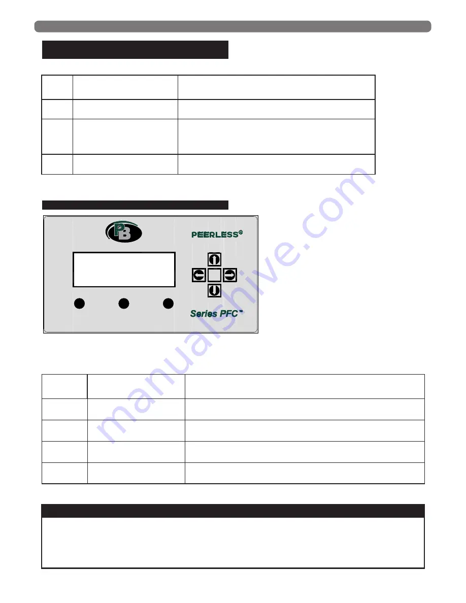
ESC

MENU

RESET

ENTER

PeerlessBoilers.com

TM

Figure 8.1: 900PB Display Buttons

Table 8.3:  Display Button Functions

All Parameter changes must be confirmed with a press of the ENTER button. 


1.  Select parameter with ENTER or RIGHT button


2.  Change parameter with UP OR DOWN buttons while parameter is flashing


3.  Confirm change with ENTER button. Parameter will stop flashing and show new setting.

NOTICE

Button

Default Screen

Menu Selection -

User/Installer Level

RESET

Reset Lockout Error

Press and hold to clear lockout errors.

MENU

Enter the Main Menu

Enter menu structures for user and installer access.

ESC

Return to the Status Overview

ARROWS

Main Screen Menus

Navigation.

Summary of Contents for PureFire PFC-625

Page 1: ...PureFire Boilers PFC 625 PFC 750 Gas Installation Operation Maintenance Manual ...

Page 2: ...R CONNECTIONS 31 C INTERNAL WIRING 32 8 BOILER CONTROL INTERNAL WIRING OPERATION 35 A CONTROL OVERVIEW 35 B AVAILABLE CENTRAL HEAT MODES 35 C AVAILABLE DOMESTIC HOT WATER MODES 36 D DISPLAY UTILIZATION 36 E USER INTERFACE MENU STRUCTURE 38 F MAIN MENU 39 G CENTRAL HEATING CH 39 H DOMESTIC HOT WATER DHW 39 I INFORMATION 39 J SETTINGS 41 K SYSTEM TEST 47 L INSTALLER MENU CODE 48 M OUTDOOR RESET OPER...

Page 3: ...ions and make special notice of potential hazards The definition of each of these categories in the judgement of PB Heat LLC are as follows USING THIS MANUAL Indicates special attention is needed but not directly related to potential personal injury or property damage NOTICE Indicates a condition or hazard which will or can cause minor personal injury or property damage CAUTION DANGER Indicates a ...

Page 4: ...ueled equipment is installed in a crawl space or an attic the hard wired carbon monoxide detector with alarm and battery back up may be installed on the next adjacent floor level Detector s must be installed by qualified licensed professionals APPROVED CARBON MONOXIDE DETECTORS Each carbon monoxide detector shall comply with NFPA 720 and be ANSI UL 2034 listed and IAS certified SIGNAGE A metal or ...

Page 5: ...f the required volumes for all appliances located within the space Rooms communicating directly with the space in which the appliances are installed and through combustion air openings sized as indicated in Subsection 3 are considered part of the required volume The required volume of indoor air is to be determined by one of two methods a Standard Method The minimum required volume of indoor air r...

Page 6: ...ustion Air Outdoor combustion air is to be provided through one or two permanent openings The minimum dimension of these air openings is 3 inches 76 mm a Two Permanent Opening Method Provide two permanent openings One opening is to begin within 12 inches 305 mm of the top of the space and the other is to begin within 12 inches 305 mm of the floor The openings are to communicate directly or by duct...

Page 7: ...ovide an adequate supply of combustion ventilation and dilution air and shall be approved by the authority having jurisdiction 8 Mechanical Combustion Air Supply a In installations where all combustion air is provided by a mechanical air supply system the combustion air shall be supplied from the outdoors at the minimum rate of 0 35 ft3 min per 1000 Btu hr 0 034 m3 min per 1000 W of the total rate...

Page 8: ...xterior of buildings shall have the lowest side of the combustion air intake opening at least 12 inches 305 mm above grade 11 Refer to Section 3 of this manual Venting Air Inlet Piping for specific instructions for piping the exhaust and combustion air E PLANNING THE LAYOUT 1 Prepare sketches and notes showing the layout of the boiler installation to minimize the possibility of interferences with ...

Page 9: ...s from the boiler to be installed on top 3 The boiler can be lifted several way with a fork lift with a chain hoist using eyebolts through the top mounting holes of the unit as shown in Figure 2 2 or by passing 5 to 10 foot 2 3 meter lengths of 1 to 1 1 4 schedule 40 or 80 pipe through the boilers frame 4 Insert washers and bolts not provided See Table 2 1 through the holes provided in the frame o...

Page 10: ... final position the cover can be removed by removing the 5 screws holding it in place This will expose the exhaust connection and drain connection on the boiler This pan serves as an optional front cabinet pan after it is removed from the rear of the boiler The pan can be inserted when the burner assembly is removed from the boiler or it can be discarded BOILER SET UP VENT COVER Figure 2 3 Removin...

Page 11: ...nces 2 Vent and air intake piping is to be installed so that there is sufficient access for routine inspection as required in Section 11 of this manual 3 The vent piping for this boiler is approved for zero clearance to combustible construction However a fire stop must be used where the vent pipe penetrates walls or ceilings 3 VENTING AIR INLET PIPING The venting system for this product is to be i...

Page 12: ...ent recirculation of flue gases to the air inlet pipe of the boiler or other adjacent appliances 7 Sidewall Venting Configuration a See Figure 3 2 for an illustration of clearances for location of exit terminals of direct vent venting systems This boiler vent system shall terminate at least 3 feet 0 9 m above any forced air inlet located within 10 ft 3 m Note This does not apply to the combustion ...

Page 13: ...cicles from forming or recirculation of exhaust gases from occurring Provide 3 feet clearance from the inside corner of adjacent walls b Figure 3 3 3 4 and 3 5 show approved sidewall venting configurations using standard PVC or CPVC fittings A similar configuration using FasNSeal stainless steel exhaust pipe can be used with either PVC or other approved material for the combustion air intake pipin...

Page 14: ...ING Figure 3 7 Vertical Exhaust Routed Through an Unused Chimney with Indoor Air EXHAUST CONNECTION 5 8 I D HOSE TO CONDENSATE TRAP AIR INLET Figure 3 9 Drain Tee and Air Inlet Connections WARNING Figure 3 8 Vertical Exhaust Routed Through an Unused Chimney with Outdoor Air 12 ...

Page 15: ...nnection to the boiler to reduce the vent condensate draining through the heat exchanger Use of an adapter from one vent material to another is permitted between the vent connection and tee The tee can be a pre fabricated component from an approved venting material manufacturer or a field made PVC assembly that is properly sealed and inspected for leakage 3 The Air Intake connection should be secu...

Page 16: ... port plug and insert the probe from a suitable combustion analyzer 3 Be sure to replace the plug before leaving the boiler unattended G BOILER REMOVAL FROM COMMON VENTING SYSTEM At the time of removal of an existing boiler follow these steps with each appliance remaining connected to the common venting system placed in operation while the other appliances remaining connected to the common venting...

Page 17: ...ilateurs aspirants registres de foyer et appareils fonctionnant au gaz 9 Any improper operation of the common venting system should be corrected so that the installation conforms with the National Fuel Gas Code ANSI Z223 1 NFPA 54 or CAN CGA B149 Installation Codes Tout fonctionnement inadéquat du système d évacuation commun doit être corrigé de manière à respecter les normes du National Fuel Gas ...

Page 18: ... a rinsing agent prior to boiler installation Any new system must be cleaned to remove any flux or welding residue Any existing system must be cleaned to remove scale and particulate matter prior to boiler connection to the system Thoroughly flush any cleaning agent from the system with clean water prior to connecting the boiler See Table 4 1 for recommended cleaning agents 4 High oxygen levels in...

Page 19: ...on in the piping system and eliminating noise 3 Expansion Tank An expansion tank such as a Bell Gossett Series HFT is required to provide room for expansion of the heating medium water or glycol solution Consult the expansion tank manufacturer s instructions for specific information regarding installation The expansion tank is to be sized for the required system volume and capacity In addition be ...

Page 20: ...n which glycol solution is used as the heating medium 8 Pressure Relief Valve The boiler pressure relief valve is shipped in the miscellaneous parts box for field installation It is extremely important to install this device The valve is to be installed on the boiler supply pipe as shown in Figure 4 2 Pipe the discharge of the relief valve to within 12 of the floor and close to a floor drain Provi...

Page 21: ...the calculation is as follows Output 612 000 Required Flow ________ _________ 61 2 GPM DT x 500 20 x 500 d The boiler pressure drop for various flow rates can be determined using Figure 4 3 PureFire Circulator Sizing Graph below WATER PIPING CONTROLS Figure 4 3 Series PFCTM Circulator Sizing Graph General Pump Primary Secondary 0 5 10 15 20 0 100 200 300 400 500 600 700 800 0 5 10 15 20 25 0 20 40...

Page 22: ...3 20 64 616 99 98 22 26 22 09 660 26 20 61 2 13 9 11 61 347 06 73 5 16 69 12 43 371 4 25 48 96 11 12 7 43 222 12 58 8 13 35 7 95 237 69 30 40 8 9 27 5 16 154 25 49 11 13 5 52 165 07 35 34 97 7 94 3 79 113 32 42 9 54 4 06 121 27 40 30 6 6 95 2 9 86 76 36 75 8 35 3 11 92 85 Table 4 7 Circulator Selection Chart General Pump Primary Secondary Piping Circulator Manufacturer DT F PFC 625 PFC 750 Taco 20...

Page 23: ...or decreased heating capacity of the fluid 6 Due to increased flow rate and fluid viscosity the circulator head requirement will increase Contact the pump manufacturer to correctly size the circulator for a particular application based on the glycol concentration and heating requirements 7 A strainer sediment trap or some other means for cleaning the piping system must be provided It should be loc...

Page 24: ...22 WATER PIPING CONTROLS Figure 4 4 Recommended Piping One Boiler with Multiple CH Zones One DHW Tank ...

Page 25: ...23 WATER PIPING CONTROLS Figure 4 5 Recommended Piping Multiple Boilers with Multiple CH Zones One DHW Tank ...

Page 26: ...24 WATER PIPING CONTROLS Figure 4 6 Alternate Piping Multiple Boilers with Multiple CH Zones Zone Valves One DHW Tank ...

Page 27: ...nt gravity flow through the boiler c See Figure 4 7 for recommended system piping for chiller operation 2 For boilers connected to heating coils in a forced air system where they may be exposed to chilled air circulation install flow control valves or other automatic means to prevent gravity circulation of the boiler water during cooling cycles See Figure 4 8 for an illustration WATER PIPING CONTR...

Page 28: ...116 8 300 235 22 000 623 50 15 2 440 12 670 19 1 270 36 2 000 57 3 600 102 7 400 210 20 000 566 60 18 3 400 11 610 17 1 150 33 1 850 52 3 250 92 6 800 193 18 000 510 70 21 3 370 10 560 16 1 050 30 1 700 48 3 000 85 6 200 176 17 000 481 80 24 4 350 10 530 15 930 26 1 500 42 2 600 74 5 400 153 15 000 425 90 27 4 320 9 490 14 870 25 1 400 40 2 500 71 5 100 144 14 000 396 100 30 5 305 9 460 13 710 20 ...

Page 29: ...esult in damage to the automatic gas valve A high gas pressure switch has been provided with the boiler to prevent high pressure conditions c The high and low gas pressure switch locations can be seen in Figure 5 1 3 To check the gas supply pressure to the gas valve a Turn off the power at the service switch b Close the gas shutoff valve c Using a flat screwdriver turn the screw inside the inlet p...

Page 30: ...hould be made only at full input rate b See Section 9 Start Up Procedure for specific information about commissioning and adjusting the boiler 4 The recommended CO2 settings are given in Table 5 5 and Table 5 6 for PFC 625 and PFC 750 respectively In no case should the boiler be allowed to operate with CO emissions higher than 200 ppm 5 Refer to Section 3 Venting and Air Inlet Piping for informati...

Page 31: ...king up into the heat exchanger b Trap the condensate to prevent combustion gases from escaping 2 Figure 6 1 shows the components of the condensate system a Condensate Collector Container This vessel is a transparent plastic container designed to catch the condensate separately from the heat exchanger and from the exhaust venting system This vessel also acts as part of the trap to prevent combusti...

Page 32: ...Pitch Be sure that the pipe or tubing is pitched away from the boiler with a slope of no less than 1 4 per foot 4 Multiple Boilers Condensate drain tubes from multiple boilers should be run separately to prevent a nuisance lockout of multiple boilers due to a single clogged drain tube 5 Condensate Pumps If the boiler drain is below the level of a gravity drain a condensate pump should be used Tabl...

Page 33: ...ower 4 L2 5 L1 Input 120 VAC Pump Supply 120 VAC 60 Hz 1 Phase supply from a fused disconnect switch to power the boiler circulators 6 L2 7 L Output 120 VAC GEN Pump General Circulation Pump Use this output to power the GEN boiler circulator 8 N 9 L Output 120 VAC DHW Pump DHW Circulation Pump Use this output to power the Domestic Hot Water DHW circulator 10 N 11 L Output 120 VAC CH Pump CH Circul...

Page 34: ... seen in Table 7 2 6 PC Communication Adapter Green Plug The PC Communication Adapter PFC7008 is detached and located inside the electrical tray below the terminals This connection allows Factory Engineers to review control settings and view advanced diagnostic features 7 Return Sensor The return sensor is located on the left side above the heat exchanger This component monitors the return tempera...

Page 35: ... to the viewer window This component is used to detect overheating of the burner plate primarily caused by broken insulation on the inside of the boiler plate Only use a factory provided Series PFC High Limit switch Burner Plate Switch 17 Air Proving Switch The air proving switch is mounted on the inner front panel above the heat exchanger on the right hand side This switch indicates that the air ...

Page 36: ...34 ELECTRICAL CONNECTIONS INTERNAL WIRING Figure 7 4 Internal Wiring Schematic for PFC 625 PFC 750 boilers ...

Page 37: ...d initiated by control logic Always present Setpoint is calculated based on the Outdoor temperature to improve fuel usage and boiler efficiency Boiler targets calculated CH setpoint and operates based on the Supply temperature hysteresis When CH demand is not present calculated setpoint decreases gradually 3 Fixed Setpoint with Permanent Demand Demand initiated by control logic Always present User...

Page 38: ...r NOTES While accessible via the Installer menu DHW modes 3 4 5 6 7 and 8 are not functional with the Series PFC boiler Numbers in parentheses refer to Boiler Parameter setting numbers See Table 8 2 J 1 ESC MENU RESET ENTER PeerlessBoilers com TM Figure 8 1 900PB Display Buttons Table 8 3 Display Button Functions All Parameter changes must be confirmed with a press of the ENTER button 1 Select par...

Page 39: ... when flashing Central Heating disabled Domestic Hot Water enabled DHW demand active when flashing Domestic Hot Water disabled Burner Active Emergency mode active Cascade Only Error Present on control Description in the bottom of the display Cascade Managing unit Cascade Dependent unit Number indicates address Frost Protection active Anti Legionella active ...

Page 40: ...nt DHW Store Setpoint DHW Store Setpoint Information Software Versions Boiler Status Boiler History Error Log Service Settings System Test Boiler Settings General Settings Boiler Parameters Module Cascade Service Language Time Date Unit Type Display Settings Time Zone Settings Cascade Mode Other Settings Central Heating CH Domestic Hot Water DHW i i Ω Aa Figure 8 3 Menu Structure ...

Page 41: ...71 0 Table 8 G 0 Central Heating CH Menu Item Function Description Units Default Value DHW Store Setpoint Set the DHW Store Setpoint for DHW Modes 1 2 O F O C 180 82 5 Table 8 H 0 Domestic Hot Water DHW Menu Item Function Description Software Versions Enter the Software Versions menu Boiler Status Enter the Boiler Status menu Boiler History Enter the Boiler History menu Error Log Enter the Error L...

Page 42: ...al Room Thermostat Status open closed Fan Speed Actual Fan Speed RPM Ionization Actual Flame Signal Ionization Current uA State Actual Burner State Standby PrePurge0 PrePurgePreIgnit Ignit FlameProving Burn PostBurn PostPurge0 PostPurge1 ExtendedPostPurge Alarm Error Actual Lock Block or Warning Error Code Calculated Setpoint Actual CH Setpoint O F O C Table 8 I 2 Information Boiler Status Menu It...

Page 43: ...Item Function Description General Settings Enter the General Settings menu Boiler Settings Enter the Boiler Settings menu Table 8 J 0 Settings Menu Item Function Description Language Enter the Language menu Unit Type Enter the Unit Type menu Date Time Enter the Date Time menu Cascade Mode Enter the Cascade Mode menu Other Settings Enter the Other Settings menu Table 8 J 1 0 Settings General Settin...

Page 44: ... of Month Select how the Day of Month is displayed 1 or 2 digits 2Digits Month Select how the Month is displayed 1 or 2 digits Short Text Full Text 2Digits Year Select how the Year is displayed 2 or 4 digits 4Digits Date Separation Character Select the Date Separation Character _ _ Day of Week Select how the Day of Week is displayed Disabled Short Text Full Text Short Text Seconds Select if Second...

Page 45: ...ings Temperature Selection Parameter Parameter Description Unit Option Default Option 1 CH Mode Set the CH Mode 0 CH with RT Input 1 CH with RT Input Outdoor Reset 2 CH with Full Outdoor Reset 3 CH with Permanent Demand 4 Analog Input for Setpoint 5 Analog Input for Power 1 CH with RT Input Outdoor Reset 3 CH Setpoint Set the CH Setpoint O F O C 159 8 71 0 109 Calc Setp Offset Set the offset for C...

Page 46: ... 0 37 DHW Tank Hyst Up Set the DHW tank hysteresis up O F O C 9 0 5 0 38 DHW Tank Supply Extra Set the DHW tank supply setpoint offset O F O C 54 0 30 0 42 DHW Priority Set the DHW priority mode 0 Time 1 Off 2 On 0 Time 43 DHW Max Priority Time Set the maximum DHW priority time min 30 44 DHW Pump Overrun Set the DHW post circulation time sec 60 48 DHW Tank Setpoint Set the DHW setpoint O F O C 120...

Page 47: ...t Input 1 Roomstat Input 125 Prog Output 1 Do Not Change Without Factory Approval Select the function for programmable output 1 0 Disabled 1 Module Pump 2 CH Pump 3 DHW Pump 4 System Pump 5 Cascade Pump 6 Alarm Relay 7 Filling Valve 8 LPG Tank 9 External Igniter 10 Air Damper 2 CH Pump 126 Prog Output 2 Do Not Change Without Factory Approval Select the function for programmable output 2 0 Disabled...

Page 48: ... Day Select the day for the anti legionella cycle Sunday Saturday Sunday 108 Anti Legionella Hour Select the time for the anti legionella cycle hrs 1 205 Frost Protection Enable Frost Protection Enabled Disabled Enabled 206 Anti Legionella Enable Anti Legionella Protection Enabled Disabled Enabled Table 8 J 2 1 cont Settings Boiler Settings Boiler Parameters Parameter Parameter Description Unit Op...

Page 49: ...modulation delay time min 10 82 Next Module Start Rate Set the next module start rate 80 83 Next Module Stop Rate Set the next module stop rate 25 84 Module Rotation Interval Set the rotation interval days 5 149 First Module to Start Set the first module to start in the rotation cycle 1 152 PwrMode2 Min Power Set the power mode 2 minimum power 20 153 PwrMode2 Hysteresis Set the power mode 2 hyster...

Page 50: ... outdoor temperature changes Figure 8 5 above visualizes the curve that is controlled by parameters 19 through 27 1 The Boiler Design Temperature 19 and Outdoor Design Temperature 20 control the maximum setpoint and the temperature at which it will be targeted 2 The Boiler Mild Weather Temperature 21 and Outdoor Mild Weather Temperature 22 control the minimum setpoint and temperature at which it w...

Page 51: ...F C 100 4 38 0 22 Mild Weather Design Outdoor Temperature Sets the Outdoor Temperature at which the boiler will target the Boiler Mild Weather Design Temperature For default Boiler will target 104 F when the outdoor temperature is 68 F F C 68 0 20 0 23 Minimum CH Setpoint Design Supply minimum limit Sets lower limit of Calculated CH setpoint Calculated CH setpoint will always be at or above this v...

Page 52: ...ol allows the unit to run at 1 input until the Stayburn temperature is reached at 193 F 88 F The boiler will always shutdown at this temperature and will never exceed it The Series PFC is not designed to run beyond this temperature Steps should be taken to improve the system to lower the required setpoint if the Stayburn Temperature is ever reached The boiler will not re ignite until the Startburn...

Page 53: ...e boiler that is connected to the system pumps and external sensors i Once a boiler is configured as the managing boiler continue on to the remaining cascade parameter options listed in Table 8 J 2 2 The remaining options are intended to operate well with most boiler systems using the default parameters However the descriptions shown allow the experienced installer or service person to modify the ...

Page 54: ...52 BOILER CONTROL INTERNAL WIRING OPERATION Figure 8 9 Multi Boiler Wiring Daisy Chain Figure 8 10 Multi Boiler Wiring Independent Connection ...

Page 55: ...e boiler 2 Open the gas shut off valve on the rear of the boiler and allow the gas header to be pressurized Press the reset buttons on both gas pressure switches to be sure that they are reset and operational The burner LCD displays on the control cabinet will read GAS PRESSURE ERROR if the gas pressure switches are not reset 3 Connect a manometer to the incoming gas line and be sure that the pres...

Page 56: ...th valves The desired CO2 for Natural Gas is 8 80 with an inlet gas pressure of nominal 7 0 INWC for both models The desired CO2 for LP gas is 10 0 with an inlet pressure of 11 w c for the PFC 625 and 9 8 for the PFC 750 The procedure for setting and adjusting the duel gas valves is as follows 1 With the boiler powered off and no call for heat possible Turn the throttle screw all the way in on one...

Page 57: ...at LLC representative I TEST HIGH LIMIT Check that the burner will shut down when the high limit circuit is open 1 On the LCD display for the Dependent burner enter the Installer Menu by pressing and holding the Select and Menu keys simultaneously for 3 seconds a Enter the Main Menu System Test Test State g Low Power b The burner will ignite and after a short stabilization period run at 1 modulati...

Page 58: ...56 J LIGHTING OPERATING INSTRUCTIONS Figure 9 1 Lighting Operating Instructions START UP PROCEDURE ...

Page 59: ...l is constant 2 Demand is applied Central Heat Radiator symbol begins flashing 3 Boiler pump and CH pump start 4 Blower begins Pre purge for 30 seconds at ignition speed 5 Spark engages 2 seconds 6 Gas valve opens 7 Spark remains engaged for 2 more seconds 8 Two second flame proving period holds valve open while control checks for flame signal 9 Boiler holds at ignition speed for 10 seconds before...

Page 60: ...uity through blower control harness 5 pin connector to J4 connector on control board If continuity is found replace control If no continuity is found replace harness 6 FAN_ERROR_TOO_SLOW Fan runs too slow for more than 60 seconds Check voltage to the blower A low voltage can cause the blower to run at the incorrect speed due to lack of power Replace blower if voltage is correct Check for continuit...

Page 61: ... Lower system setpoint to decrease flue temperature Check temperature delta across the boiler supply and return A low delta will cause increased flue temperatures due to poor energy transfer 17 STACK_ERROR Internal software error Replace Control 18 INSTRUCTION_ERROR Internal software error Replace Control 19 ION_CHECK_FAILED Internal software error Replace Control 20 FLAME_OUT_TOO_LATE Flame still...

Page 62: ... GAS_PRESSURE_ERROR Gas pressure switch is open for more than E2_GPS_Timeout Is the gas pressure within the range listed on the nameplate Press the reset buttons on each of the gas pressure switches located on the gas line inside the jacket 37 AIR_DAMPER_LOCKING More than 3 consecutive Air_Damper_Error have occurred 38 FLUE_PRESSURE_LOCKING More than 3 Blocked Flue Condensate Switch in 24 hours Ch...

Page 63: ...ector cap Check for blockages in the condensate system inside or after the condensate trap A slow drainage of condensate could cause condensate back up that will trip this switch under certain conditions Clean condensate system Check for broken wires or bad connections 118 WD_COMM_ERROR Watchdog communication error If error persists replace control 119 RETURN_OPEN Return Sensor open Check sensor w...

Page 64: ...tance should be between 15 kΩ and 500 Ω If no resistance is present replace sensor 132 OUTDOOR_SHORTED Outdoor Sensor Shorted Check for resistance through the sensor by touching meter lead across both pins on the sensor Resistance should be between 15 kΩ and 500 Ω If no resistance is present replace sensor 133 NET_FREQ_ERROR Net freq error detected by the watchdog If error persists replace control...

Page 65: ...emand needs to be stopped with fan at ignition speed but no error needed to be stored at this time 165 VSUPPLY_TOO_LOW Main supply voltage too low for more than 60 seconds Check supply voltage for values below 102 Volts 166 VSUPPLY_TOO_HIGH Main supply voltage too high for more than 60 seconds Check supply voltage or values above 132 Volts ...

Page 66: ...liance model selection using Table 8 5 2 1 in this manual 204 OUTDOOR_WRONG Outdoor sensor is either open or shorted Remove the wires from terminals 30 31 on the boiler and check the resistance between them If this reading is below 3000Ω check the reading at the sensor If the reading is the same at the sensor replace the sensor If this reading is higher at the sensor replace the wiring 205 T_SYSTE...

Page 67: ... been classified by the International Agency for Research on Cancer IARC as a possible carcinogen to humans After the RCF materials have been exposed to temperatures above 1800 F they can change into crystalline silica which has been classified by the IARC as carcinogenic to humans If particles become airborne during service or repair inhalation of these particles may be hazardous to your health A...

Page 68: ...r as described in Section E below Replace the burner if necessary 7 With the boiler in operation check that condensate is dripping from the condensate tubing Check for any blockage or restriction in the condensate drain lines D CONDENSATE SYSTEM CLEANING INSTRUCTIONS 1 Removal of Condensate Container a Close the manual gas shutoff valve at the rear of the boiler and turn off the burner service swi...

Page 69: ...dup then vacuum the debris from the coils 4 Spray coils with clear water making sure to confine the spray to the area being cleaned try to avoid wetting the back ceramic wall of the unit Flush the combustion chamber with fresh water At this point the Series PFCTM should be ready to power back up 5 Reinstall the burner plate assembly using the following steps a Inspect the inside of the heat exchan...

Page 70: ...h Power PFC 625 625 183 2 Natural Gas 2700 3500 7250 LP Gas 2600 7300 PFC 750 750 219 8 Natural Gas 2650 3500 7350 LP Gas 2700 7400 Table 12 1 Boiler Ratings SERIES PFCTM BOILER RATINGS Series PFCTM Boiler Model Input Gross Output Net Water Ratings Thermal Efficiency Minimum Maximum MBH kW MBH kW MBH kW MBH kW PFC 625 125 36 6 625 183 2 612 179 4 532 2 156 97 9 PFC 750 150 43 9 750 219 8 735 215 4...

Page 71: ...at 77 F 25 C 14 F 10 C to 244 F 118 C Flue 12kΩ at 77 F 25 C 50 F 10 C to 280 F 138 C Header 12kΩ at 77 F 25 C 14 F 10 C to 244 F 118 C Outdoor 12kΩ at 77 F 25 C 40 F 40 C to 185 F 85 C Optional Sensors DHW 12kΩ at 77 F 25 C 14 F 10 C to 244 F 118 C System 12kΩ at 77 F 25 C 14 F 10 C to 244 F 118 C Standards North America ANSI Z21 20 CSA C22 2 Europe CE EN298 BOILER DIMENSIONS RATINGS Table 12 4 S...

Page 72: ...from Parts To Your Door at 1 610 916 5380 www partstoyourdoor com Note Remember to include the boiler model number and serial number when ordering parts 13 REPAIR PARTS 26 25 24 23 16 15 5 19 14 18 17 4 3 5 6 12 20 21 20 22 5 5 2 1 10 9 8 7 11 5 13 Figure 13 1 Heat Exchanger Repair Parts ...

Page 73: ...ng Bracket 1 54885 12 Gasket Intake Manifold to Burner 1 54884 13 Burner Bluejet 1 54870 54871 14 Combustion Chamber Cover Plate 1 54869 15 Insulation Combustion Chamber Cover Plate 1 54877 16 Gasket Siliconized Fiberglas Braid 1 54876 17 Screw M10 x 20 6 54874 18 Washer M10 6 54873 19 Burner Door Insulation Clip 4 54879 20 Gasket Sight Glass 2 54880 21 Sight Glass Lens 1 54881 22 Sight Glass Plat...

Page 74: ...72 REPAIR PARTS 3 1 4 5 6 8 6 9 10 11 12 11 10 9 8 6 7 13 14 15 16 17 18 21 22 19 20 19 2 23 24 Figure 13 2 Blower Gas Train Assembly ...

Page 75: ... 5926 6 Nipple 1 x 1 1 2 Close SCH40 Black 3 99212 7 Tee 1 1 424 8 Street Elbow 1 x 3 4 Black 2 7064 9 90 Flange Kit 3 4 NPT 2 5543 N S Screw Gas Valve to Flange M5 x 30 Hex Skt HD 4 Local Hardware N S Screw Gas Valve to Flange M5 x 12 Hex Skt HD 4 Local Hardware N S O Ring 90 Flange 2 10 Gas Valve GB WND 057 2 54429 11 Straight Flange Kit 3 4 NPT 2 5855 N S Screw Gas Valve to Flange M5 x 12 Hex S...

Page 76: ...74 REPAIR PARTS 2 9 8 7 2 4 2 1 3 6 6 5 2 10 5 Figure 13 3 Supply Return Piping ...

Page 77: ... 2 Elbow 2 BLK 4 443 3 Return Sensor TSD00BS 1 54418 4 Nipple 2 x 5 5 NPT with 1 4 NPT Hot Tap 1 PFC1001 5 Adapter NPT x GRV 2 PFC1000 6 Coupling Slidelok 2 Rigid 2 5921 7 LWCO Probe 35mm 1 54834 8 Dual Supply Sensor TSD01AS 1 54634 9 Nipple 2 x 19 NPT with 2 1 4 NPT Tap 1 PFC1002 10 Nipple 2 x 2 1 2 1 99262 ...

Page 78: ...76 REPAIR PARTS 18 16 17 6 14 15 9 4 3 1 8 13 18 7 19 2 10 11 12 5 Figure 13 4 Jacket Assembly ...

Page 79: ...r Box Heat Exchanger Cabinet 1 PFC5001 8 Air Box Venturi Cabinet 1 PFC5000 9 Air Box Venturi Cabinet Cover 1 PFC5002 10 Air Inlet Box 1 PFC5003 11 Rear Electrical Box 1 PFC2012 12 Rear Electrical Box Cover 1 PFC2013 13 Condensate Pan 1 PFC2009 14 Blower Cabinet Pan 1 PFC2007 15 Blower Cabinet Pan Support 1 PFC2008 N A 16 Front Panel Mounting Bracket Left Hand 1 PFC2003 17 Front Panel Mounting Brac...

Page 80: ...PAIR PARTS Figure 13 5 Electrical Tray Control Locations 1 13 10 9 8 5 2 7 6 3 4 11 10 9 14 12 11 11 11 4 11 11 THIS WIRE LATCH GATE GOES IN FROM THE BOTTOM SIDE THE REMAINING LATCHES GO IN FROM THE TOPSIDE ...

Page 81: ...e Holder Top Entry 3 5917 5 Pump Relay Module 10A 1 54556 6 Track Pump Relay Module 1 54551 7 Screw 6 32 X 1 2 PHIL 2 5449 8 Terminal Block 6 Pole 6 5547 9 Spacer Nylon 25 OD X 141 ID X 281 L 9 5448 10 Nut Hex 6 32 9 51553 11 Wire Holder Latching Side Entry 9 5916 12 Spacer Nylon 217 OD X 147 ID X 230 L 7 5931 13 User Interface Display PFC 625 750 1 54868 14 Bushing Snap 7 8 2 5438 ...

Page 82: ...80 REPAIR PARTS Figure 13 6 Condensate System 1 2 4 7 5 15 15 8 11 3 10 15 6 15 15 12 15 13 15 9 15 14 15 ...

Page 83: ... 4 Tubing 1 OD x 3 4 ID 22 5417 5 Tubing 1 OD x 3 4 ID 3 5417 6 Tubing 1 OD x 3 4 ID 3 5417 7 Tubing 7 8 OD x 5 8 ID 26 5416 8 Tubing 5 16 OD x 3 16 ID 18 5563 9 Hose Barb Tee 3 4 x 3 4 x 3 4 1 5915 10 Hose Barb Tee 3 4 x 3 4 x 1 2 NPT 1 5913 11 90 degree Hose Barb 1 4 x 1 2 NPT 1 5914 12 Condensate Drain Tube 1 5420 13 Bulk Head Fitting 1 54140 14 Clamp Stainless Steel 8897T23 1 5938 15 Hose Clam...

Page 84: ...82 REPAIR PARTS Figure 13 7 Wiring Harnesses PFC7001 PFC7002 PFC7007 PFC7004 PFC7003 PFC7008 PFC7010 PFC7011 54298 ...

Page 85: ... CODE PFC7001 PFC7002 PFC7003 PFC7004 PFC7007 PFC7008 LINE TYPE DESCRIPTION BLOWER CONTROL J4 LOW VOLTAGE RIGHT SIDE POWER RIGHT SIDE GAS VALVE NAT LP GAS VALVE FLAME SENSOR J5 PC COM ARGUS LINK ADAPTER 54298 PFC7010 PFC7011 IGNITION CABLE IGNITION GROUND WIRE CONTROL GROUND WIRE ...

Page 86: ...acture Date Conversion Date Pressure Readings Inlet Gas Pressure Static in w c Inlet Gas Pressure Drop at Startup in w c High Fire Inlet Gas Pressure in w c Low Fire Inlet Gas Pressure in w c Combustion Readings Flame Signal High Fire µA Flame Signal Low Fire µA CO2 High Fire CO2 Low Fire CO High Fire ppm CO Low Fire ppm Fan Speed High Fire RPM Fan Speed Low Fire RPM Exhaust Temperatures Exhaust T...

Page 87: ...85 SERVICE LOG SERVICE LOG Date Serviced By Description of Service Serial Number ...

Page 88: ...he owner and must be affixed near the boiler for future reference TO THE OWNER This boiler should be inspected annually by a Qualified Service Agency PFC8024 R0 07 21 3C Printed in U S A 2021 PB Heat LLC All rights reserved PB HEAT LLC 131 S CHURCH STREET BALLY PA 19503 PFC 625 PFC 750 PureFire CONTROLS ...

Reviews: