69
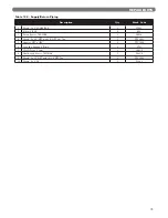
Table 12.3: Series PFC
TM
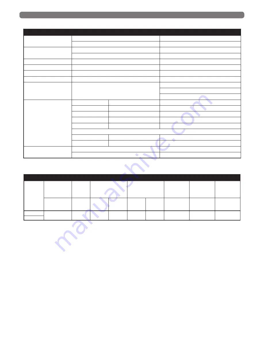
Main Control Specifications
SERIES PFC
TM
MAIN CONTROL SPECIFICATIONS
Power Supply
Voltage
120 VAC Nominal (102-132 VAC)
Frequency
60 Hz Nominal (40 Hz to 70 Hz) Phase Neutral
Fuses
Primary Control
5AT, 250 VAC (Type GDG)
Pump Relay (2)
10 Amp, 250 VAC
Blower
Voltage
120 VAC/8.5 Amps AC RMS
Gas Valve
Voltage
120 VAC
Thermostat Contacts
Voltage
24 VAC
DHW Contacts
Voltage
24 VAC
Flame Current Limits
Current
Minimum (running): 1.0 μA
Minimum (ignition): 1.5 μA
Maximum: 10.0 μA
Temperature
Sensors
NTC Thermistors
Dual Supply
10kΩ at 77°F (25°C)
14°F (-10°C) to 244°F (118°C)
Return
12kΩ at 77°F (25°C)
14°F (-10°C) to 244°F (118°C)
Flue
12kΩ at 77°F (25°C)
50°F (10°C) to 280°F (138°C)
Header
12kΩ at 77°F (25°C)
14°F (-10°C) to 244°F (118°C)
Outdoor
12kΩ at 77°F (25°C)
-40°F (-40°C) to 185°F (85°C)
Optional Sensors
DHW
12kΩ at 77°F (25°C)
14°F (-10°C) to 244°F (118°C)
System
12kΩ at 77°F (25°C)
14°F (-10°C) to 244°F (118°C)
Standards
North America
ANSI Z21.20 / CSA C22.2
Europe
CE EN298
BOILER DIMENSIONS & RATINGS
Table 12.4: Series PFC
TM
Electrical Ratings and Specifications
SERIES PFC
TM
ELECTRICAL RATINGS AND SPECIFICATIONS
Boiler
Model
Supply
Voltage
(-15%, +10%)
Frequency
(±10%)
Blower
Gas
Valve
Total Control
Circuit Max.
Current
Circulating
Pumps Max.
Current
Total Pump
Circuit Max.
Current
(VAC)
(Hz)
Voltage
(VAC)
Current
(Amps)
Voltage
(VAC)
Current
(Amps)
(Amps)
(Amps)
(Amps)
PFC-625
120
60
120
8.5
120
0.21 x 2
5.0
10.0 x 2
20.11
PFC-750


