


48
BOILER CONTROL: INTERNAL WIRING & OPERATION
L. INSTALLER MENU CODE
The Installer access only Menus are accessible by
inputting the proper PIN number into the PASSWORD
screen of the User Menu. The following menus require the
Installer Password to access:
Boiler Parameters
Module Cascade Settings
Settings
g
Boiler Settings
g
BOILER PARAMETERS
Settings
g
Boiler Settings
g
MODULE CASCADE
SETTINGS
Use the “
h
” and “
i
” buttons to select the proper number
for the flashing place in the PIN. Pressing ENTER or
RIGHT will advance to the next digit. If an incorrect
number is selected, press “
f
” to reselect.
Once the 4-digit passcode has been entered, press
“ENTER” or “
g
” once to display the Installer access only
menus.
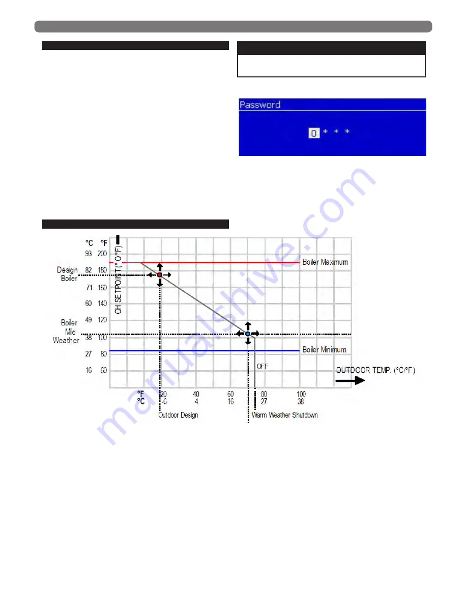
M. OUTDOOR RESET OPERATION
All Series
PFC™
boilers come with the default Central
Heat mode set to outdoor reset with room thermostat
(ODR). This feature uses the information from the
provided Outdoor Sensor to automatically adjust the
boiler setpoint based on the required heat load on the
building as the outdoor temperature changes. Figure 8.5
above visualizes the curve that is controlled by parameters
19 through 27.
1. The Boiler Design Temperature (19) and Outdoor
Design Temperature (20) control the maximum
setpoint and the temperature at which it will be
targeted.
2. The Boiler Mild Weather Temperature (21) and
Outdoor Mild Weather Temperature (22) control the
minimum setpoint and temperature at which it will be
targeted.
3. The Minimum CH setpoint (23) controls how low the
calculated setpoint can fall.
4. The maximum CH setpoint (24) controls how high the
calculated setpoint can rise when boost is active.
5. The Mild Weather Shutdown Temperature (25) allow
for control over what outdoor temperature the boiler
will begin ignoring CH demands.
6. The Boost Function Increment (26) allows for control
over how aggressively the Boost function will increase
the calculated setpoint after the boost delay is met.
7. The Boost Function Delay allows for control over the
timeframe the CH demand must be present without
the call being satisfied before the Boost Function will
begin increasing the calculated setpoint.
Installer Code is 0231
NOTICE
Figure 8.5: Outdoor Reset Curve Logic
Figure 8.4: Installer Menu Password Screen


