


Group F04: V/F Control Parameters
Group F04 is valid only for V/F control.
The V/F control mode is applicable to low load applications (fan or pump) or applications
where one AC drive operates multiple motors or there is a large difference between the AC
drive power and the motor power.
Chapter 6 Description of Function Codes
Function
code
Name
Description
(setting range)
Factory
Default
Change
F04.00
Motor1 V/F curve setting
0: linear V/F
1: multi-point V/F
2: square V/F
3: V/F complete seperation
4: V/F half seperation
5:1.2 square V/F
6: 1.4 square V/F
7: 1.6 square V/F
8: 1.8 square V/F
0
※
0: Linear V/F
It is applicable to common constant torque
load.
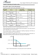
1: Multi-point V/F
It is applicable to special load such as dehydrator and centrifuge. Any such V/F curve can be
obtained by setting parameters of F04.03 to F04.08.
2: Square V/F
It is applicable to centrifugal loads such as fan and pump.
3: V/F complete separation
In this mode, the output frequency and output voltage of the AC drive are independent. The
output frequency is determined by the frequency source, and the output voltage is determin-
ed by "Voltage source for V/F separation" (F04.13).
It is applicable to induction heating, inverse power supply and torque motor control.
4: V/F half separation
In this mode, V and F are proportional and the proportional relationship can be set in F04.13.
The relationship between V and F are also related to the rated motor voltage and rated motor
frequency in Group F02.
Assume that the voltage source input is X (0 to 100%), the relationship between V and F is:
V/F = 2 * X *(Rated motor voltage)/(Rated motor frequency)
-114-
C
h
a
p
te
r
6
Peaco Support FC280 Series VFD User Manual
www.peacosupport.com [email protected] Free Shipping Worldwide Reliable Supplier
PEACO SUPPORT


