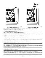
d. Insert assembled combustion-air inlet pipe into intake housing.
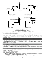
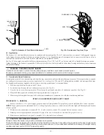
e. Make sure elbow is oriented in an acceptable direction and that the minimum clearance of 3 in. is observed. (See Fig. 50.)
f. Drill a 1/8-in. hole in 2-in. combustion-air inlet pipe using hole in intake housing as a guide.
g. Install a field-supplied No. 6 or No. 8 sheet metal screw into combustion-air pipe.
NOTE:
Do not attach combustion-air intake pipe permanently to combustion-air intake housing since it may be necessary to remove pipe for
service of igniter or flame sensor.
COMBUSTION-AIR INTAKE HOUSING PLUG FITTING
The combustion-air intake plug fitting must be installed in unused combustion-air intake housing. This fitting must be attached by using
RTV sealant, or by drilling a 1/8-in. hole in fitting, using hole in intake housing as a guide. Install a field-supplied No. 6 or No. 8 sheet
metal screw.
NOTE:
DO NOT OVERTIGHTEN SCREW. Breakage of intake housing or fitting may cause air leakage to occur.
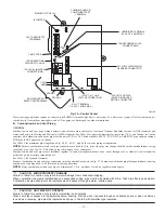
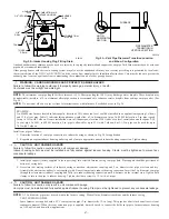
A plugged drain connection has been provided on this fitting for use when moisture is found in combustion-air intake pipe and combustion
box. If use of this drain connection is desired, drill out fitting’s tap plug with a 3/16-in. drill and connect a field-supplied 3/8-in. tube. This
tube should be routed to open condensate drain for furnace and A/C (if used), and should be trapped. (See Fig. 52.)
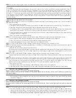
VENT PIPE
NOTE:
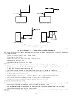
Furnace vent pipe connections are sized for 2-in. pipe. Any vent pipe size change should be made outside furnace casing in vertical pipe.
(See Fig. 53.) This allows proper drainage of vent condensate.
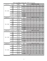
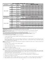
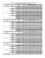
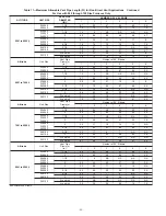
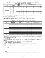
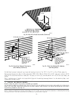
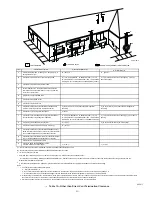
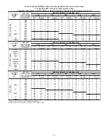
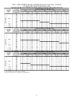
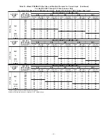
Determine vent pipe diameter and maximum pipe lengths using Table 11.
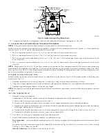
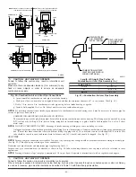
Furnace vent pipe connection must be attached as shown in Fig. 50. Inducer housing alternate vent cap may need to be relocated in some
applications.
NOTE:
Starting at furnace, slope vent pipe a minimum of 1/4 in. per linear ft upward to termination(s) with no sags between hangers.
CAUTION: UNIT MAY NOT OPERATE
Failure to follow this caution may result in intermittent unit operation.
When vent pipe is exposed to temperatures below freezing, such as when it passes through an unheated space or when a chimney
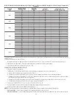
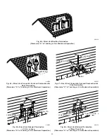
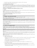
is used as a raceway, pipe must be insulated as described in Table 10 with Armaflex-type insulation.
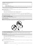
Fig. 50—Combustion-Air and Vent Pipe Connections
CAUTION: UNIT MAY NOT OPERATE
Failure to follow this caution may result in intermittent unit
operation.
Make sure there is adequate clearance (3-in. minimum) to any
fixed or loose objects in order to ensure an adequate
combustion-air supply.
A96188
COMBUSTION-
AIR
COMBUSTION-
AIR
AIR
FLOW
VENT
VENT
VENT
AIR
FLOW
AIR
FLOW
AIR
FLOW
UPFLOW
DOWNFLOW
HORIZONTAL-LEFT DISCHARGE
HORIZONTAL-RIGHT DISCHARGE
Select 1 vent pipe connection and
1 combustion-air pipe connection.
COMBUSTION-
AIR
COMBUSTION-
AIR
COMBUSTION-
AIR
COMBUSTION-
AIR
NOTE:
Select 1 vent pipe connection and
1 combustion-air pipe connection.
NOTE:
VENT
VENT
VENT
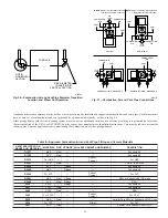
Fig. 51—Combustion-Air Inlet Pipe Assembly
Length of Straight Pipe Portion of
Combustion-Air Inlet Pipe Assembly (In.)
CASING WIDTH
A
17-1/2
8-1/2
±
1/2
21
10-1/2
±
1/2
24-1/2
12
±
1/2
A96211
FIELD-SUPPLIED
2-IN. DIAMETER
PVC PIPE
FIELD-SUPPLIED
2-IN. DIAMETER
PVC 90
°
ELBOW
COMBUSTION-AIR DISC
(FACTORY-SUPPLIED IN
LOOSE PARTS BAG)
A
—46—
Summary of Contents for PG9MAA
Page 70: ... 70 ...
Page 71: ... 71 ...

