C.
Vent Termination
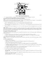
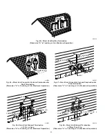
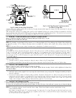
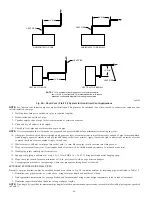
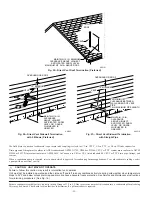
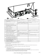
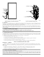
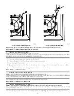
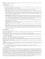
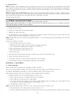
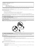
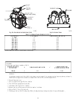
Vent pipe must terminate either through roof or sidewall. See Table 13 for required clearances. See Fig. 55, 56, or 57 for exterior piping
arrangements.
Consideration of the following should be made when determining an appropriate location for termination:
1. Comply with all clearance requirements stated in Table 13.
2. Termination should be positioned where vent vapors will not damage plants/shrubs or air conditioning equipment.
3. Termination should be positioned where it will not be damaged by or subjected to foreign objects such as stones, balls, etc.
4. Termination should be positioned where vent vapors are not objectionable.
D.
Multiventing
When 2 or more PG9MAA Furnaces are vented near each other, each furnace must be individually vented. NEVER common vent or breach vent
PG9MAA furnaces.
PROCEDURE 9—CONDENSATE DRAIN
A.
General
Condensate trap is shipped installed in the blower shelf and factory connected for UPFLOW applications. Condensate trap must be RELOCATED
for use in DOWNFLOW and HORIZONTAL applications.
Condensate trap MUST be used for all applications.
An external trap is not required when connecting the field drain to this condensate trap.
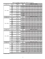
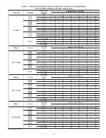
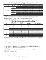
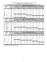
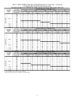
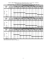
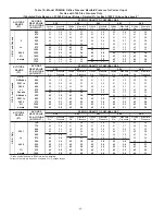
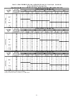
Table 11—Maximum Allowable Vent Pipe Length (Ft) for Non-Direct Vent Applications
Continued
For Use with 040 through 120 Size Furnaces Only
ALTITUDE
UNIT SIZE
VENT PIPE
DIAMETER
(IN.)*
NUMBER OF 90° ELBOWS
1
2
3
4
5
6
9001 to 10,000‡
024040
036040
1-1/2
42
37
32
27
25
20
2
57
55
53
51
49
47
024060
036060
048060
2
45
40
38
33
31
29
036080
048080
060080
2
30
25
14
9
7
NA
2-1/2
57
55
53
51
49
47
048100
060100
2-1/2
21
13
5
NA
NA
NA
3
54
49
44
39
34
29
060120
4† no disk
10
5
NA
NA
NA
NA
* Wide radius elbow.
† Vent sizing for Canadian installations over 4500 ft (1370 m) above sea level are subject to acceptance by the local authorities having jurisdiction.
NA—Not Allowed; pressure switch will not make.
NOTES:
1. Do not use pipe size greater than those specified in table or incomplete combustion, flame disturbance, or flame sense lockout may occur.
2. Assume two 45° elbows equal one 90° elbow. Long radius elbows are desirable and may be required in some cases.
3. Elbows and pipe sections within the furnace casing and at the vent termination should not be included in vent length or elbow count.
4. The minimum pipe length is 5 ft for all applications.
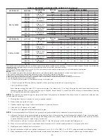
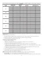
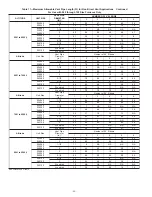
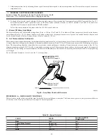
Table 12—Maximum Allowable Exposed Vent Pipe Length (Ft) With and Without Insulation
in Winter Design Temperature Ambient for Non-Direct Vent Applications*
UNIT
SIZE
WINTER DESIGN
TEMPERATURE
(°F)
MAX PIPE
DIAMETER
(IN.)
WITHOUT
INSULATION
WITH 3/8-IN. OR
THICKER INSULATION†
040
20
1-1/2
51
70
0
1-1/2
28
70
-20
1-1/2
16
70
060
20
2
65
70
0
2
35
70
-20
2
20
70
080
20
2-1/2
70
70
0
2-1/2
47
70
-20
2-1/2
28
70
100
20
3
70
70
0
3
50
70
-20
3
28
70
120
20
4
70
70
0
4
48
70
-20
4
23
70
* Pipe length (ft) specified for maximum pipe lengths located in unconditioned spaces. Pipes located in unconditioned space cannot exceed total allowable pipe length as
specified in Table 12.
† Insulation thickness based on R value of 3.5 per in.
—51—
Summary of Contents for PG9MAA
Page 70: ... 70 ...
Page 71: ... 71 ...

