Maintain a 1-in. clearance from combustible materials to supply air ductwork for a distance of 36 inches horizontally from the furnace. See NFPA
90B or local code for further requirements.
These furnaces SHALL NOT be installed directly on carpeting, tile, or any other combustible material other than wood flooring. In downflow
installations, factory accessory floor base MUST be used when installed on combustible materials and wood flooring. Special base is not required
when this furnace is installed on manufacturer’s Coil Assembly Part No. CD5 or CK5, or when Coil Box Part No. KCAKC is used.
The PG9M 040 through 120 size units are CSA (formerly CGA and AGA) design-certified for use in manufactured (mobile) homes when factory
accessory conversion kit is used. The 140 size unit is NOT design-certified for use in manufactured (mobile) homes. These furnaces are suitable
for installation in a structure built on site or a manufactured building completed at final site. The design of this furnace line is NOT CSA
design-certified for installation in recreation vehicles or outdoors.
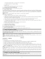
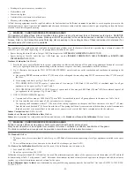
This furnace is designed for continuous return-air minimum temperature of 60°F db or intermittent operation down to 55°F db such as when used
with a night setback thermostat. Return-air temperature must not exceed 80°F db. Failure to follow these return-air limits may affect reliability
of heat exchangers, motors and controls. (See Fig. 4.)
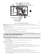
These furnaces are shipped with the drain and pressure tubes connected for UPFLOW applications. Minor modifications are required when used
in DOWNFLOW, HORIZONTAL RIGHT, or HORIZONTAL LEFT (supply-air discharge direction) applications as shown in Fig. 3. See details
in Applications section.
Install this furnace only in a location and position as specified in LOCATION and INSTALLATION sections of these instructions.
Combustion products must be discharged outdoors. Connect this furnace to an approved vent system only, as specified in the Combustion Air and
Vent piping sections of these instructions.
Never test for gas leaks with an open flame. Use a commercially available soap solution made specifically for detection of leaks to check all
connections as specified in the GAS PIPING section of these instructions.
Always install the furnace to operate within the furnace’s intended rise range with a duct system which has an external static pressure within the
allowable range as specified in the SET TEMPERATURE RISE section of these instructions.
When a furnace is installed so that supply ducts carry air circulated by the furnace to areas outside the space containing the furnace, the return
air shall also be handled by ducts sealed to the furnace casing and terminating outside the space containing the furnace.
A gas-fired furnace for installation in a residential garage must be installed as specified in the Hazardous Locations section of these instructions.
The furnace is not to be used for temporary heating of buildings or structures under construction unless the furnace installation and operation
complies with the first CAUTION in the LOCATION section of these instructions.
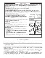
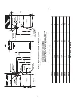
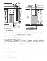
Fig. 3—Multipoise Orientations
A93041
UPFLOW
DOWNFLOW
HORIZONTAL
LEFT
AIRFLOW
AIRFLOW
AIRFLOW
AIRFLOW
HORIZONTAL
RIGHT
→
Fig. 4—Return-Air Temperature
A05004
60
0
—5—
→
→
→
→
→
→
→
→
Summary of Contents for PG9MAA
Page 70: ... 70 ...
Page 71: ... 71 ...


