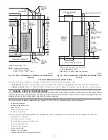
Direct venting applications require a dedicated (one PG9MAA furnace only) direct vent system. In a direct vent system, all air for combustion is
taken directly from outdoor atmosphere, and all flue gases are discharged to outdoor atmosphere.
B.
Combustion-Air and Vent Piping
GENERAL
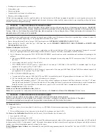
Combustion-air and vent pipe, fittings, primers, and solvents must conform to American National Standards Institute (ANSI) standards and
American Society for Testing and Materials (ASTM) standards. See Table 8 for approved materials for use in the U.S.A. and Canada. In Canada
construct all combustion-air and vent pipes for this unit of CSA or ULC listed schedule-40 PVC, PVC-DWV or ABS-DWV pipe and pipe cement.
SDR pipe is NOT approved in Canada.
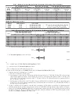
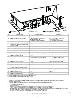
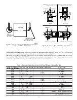
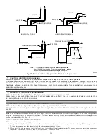
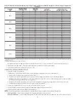
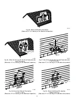
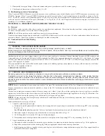
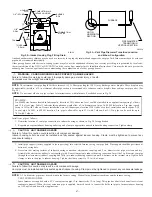
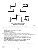
See Table 9 for maximum pipe lengths and Fig. 40, 41, 42, 43, and 44 for exterior piping arrangements.
NOTE:
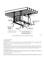
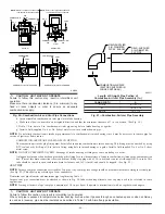
Furnace combustion-air and vent pipe connections are sized for 2-in. pipe. Any pipe size change should be made outside furnace casing
in vertical pipe. (See Fig. 36.) This allows proper drainage of vent condensate.
Combustion-air and vent pipes must terminate together in same atmosphere pressure zone, either through roof or sidewall (roof termination
preferred), using accessory termination kit.
See Table 7 for required clearances.
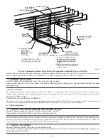
Furnace combustion-air and vent pipe connections must be attached as shown in Fig. 37. Combustion-air intake plug fitting and inducer housing
alternate vent cap may need to be relocated in some applications.
NOTE:
Slope combustion-air and vent pipes a minimum of 1/4 in. per linear ft with no sags between hangers.
CAUTION: MINOR PROPERTY DAMAGE
Failure to follow this caution may result in water damage from condensate dripping.
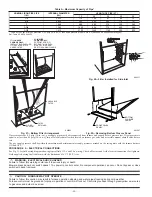
When combustion-air pipe is installed above a suspended ceiling, pipe must be insulated with 3/8-in. thick Armaflex-type insulation.
Combustion-air pipe should also be insulated when it passes through a warm, humid space.
CAUTION: UNIT MAY NOT OPERATE
Failure to follow this caution may result in intermittent unit operation.
When vent pipe is exposed to temperatures below freezing, such as when it passes through an unheated space or when a chimney
is used as a raceway, pipe must be insulated as shown in Table 8 with Armaflex-type insulation.
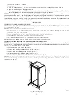
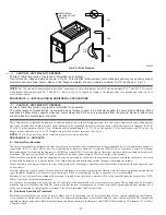
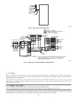
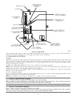
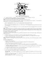
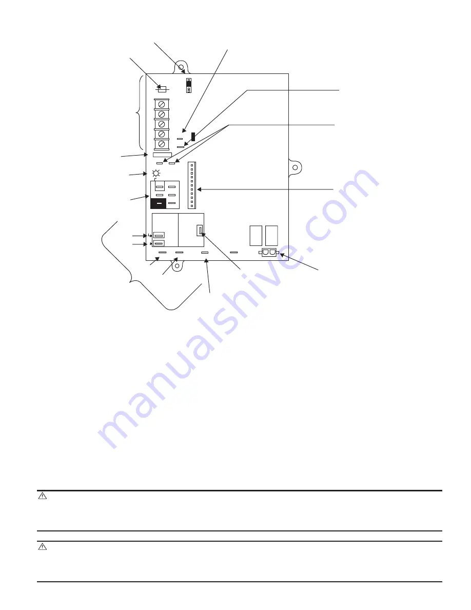
Fig. 35—Control Center
A02100
BL
W
NUETRAL
ST
A
TUS CODE LED
SEC-2 SEC-1
EAC-2 L2
FUSE 3-AMP
0.5 AMP@24VAC
HUM
TEST/TWIN
G Com
W
Y R
24V
120 180
90 150
BLOWER OFF-DELAY
PL
T 1
COOL HEA
T
SPARE-1 SPARE-2
EAC-1
1-AMP@
115VAC
PR-1
L1
PL2 1
24-V THERMOSTAT
TERMINALS
3-AMP FUSE
LED OPERATION &
DIAGNOSTIC LIGHT
115-VAC(L2)NEUTRAL
CONNECTIONS
COOL
HEAT
SPARE-1
SPARE-2
BLOWER SPEED
SELECTION TERMINALS
EAC-1 TERMINAL
(115-VAC 1.0 AMP MAX.)
115 VAC (L1) LINE
VOLTAGE CONNECTION
PL2-HOT SURFACE
IGNITER & INDUCER
MOTOR CONNECTOR
PL1-LOW VOLTAGE MAIN
HARNESS CONNECTOR
TRANSFORMER 24-VAC
CONNECTIONS
HUMIDIFIER TERMINAL
(24-VAC 0.5 AMP MAX.)
TWINNING AND/OR
COMPONENT TEST
TERMINAL
BLOWER OFF-DELAY
J2
J2 JUMPER
PL
T
—33—
Summary of Contents for PG9MAA
Page 70: ... 70 ...
Page 71: ... 71 ...

