


Appendix D Ð EMC Installation Guidelines
5 1
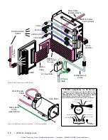
At the drive end, run the motor cable down to the
mounting panel, expose a short length of braiding and
anchor to the panel with a P-clip. The ZETA Series
require a safety earth connection to the motor (see green
and yellow striped wire in Figure 4) Ñ take this from the
stud or bus bar. Run the safety earth lead alongside the
motor lead. Note that the motor cable should be kept away
from I/O cables carrying control signals.
Motor Cables
For 10 foot (replacement) cable lengths, use 4-core 1mm
2
(AWG 18) (SWG 20) braided screen cable for the motor
connections on the ZETA6104. At the drive end, fit a
ferrite absorber over the cable before wiring to the motor
connector. Locate the absorber as close as possible to the
connector using heat-shrink sleeving.
All after-market motor connections must be made using a
high quality braided-screen cable. Cables using a
metallized plastic foil for an earth screen are unsuitable and
provide very little screening. Terminating to the screen in
a mechanically stable manner is difficult because the
screen itself is comparatively fragile Ñ bending it in a
tight radius can seriously affect the screening performance.
There must be no break in the 360
°
coverage that the
screen provides around the cable conductors. If a connector
must be used it should retain the 360
°
coverage, possibly
by the use of an additional metallic casing where it passes
through the bulkhead of the enclosure. The cable screen
must
not
be connected to the cabinet at the point of entry.
Its function is to return high-frequency chopping current
back to the drive or controller. This may require mounting
the connector on a sub-panel insulated from the main
cabinet, or using a connector having an internal screen
which is insulated from the connector housing.
Within the cabinet itself, all the motor cables should lie in
the same trunking as far as possible. They must be kept
separate from any low-level control signal cables. This
applies particularly where the control cables are unscreened
and run close to the drive or other sources of electrical noise.
Motor Feedback Cables
Feedback devices such as encoders, tachometers and Hall
effect sensors also require the use of high-quality braided
screen cable. If it is necessary to replace the standard
feedback cable, select a braided screen cable that matches
the gage of the devices original cable and attach as close to
the transducer as possible. Avoid complex and bulky
connections that can cause degradation in feedback signal
quality. If possible, use in-line cable splicing techniques,
and cover the splice point with heat-shrink tubing.
Remove a section of the braided shield cableÕs insulation
to expose the braid, and tie the braid to earth using the
same P-clip 360
°
bond as shown in Figure 2. Differential
signals should use twisted pair cable to minimize
magnetic coupling. At the receiving end, fit a ferrite
absorber over the feedback cable before wiring the
connector, then P-clip the braid to a suitable ground (metal
back-plane of drive mounting panel, or earth point of
device that receives the feedback)Ñ see Figure 3.
Step Motors
It is preferable to use motors with screw terminations
whenever possible. If flying-lead motors are used, it is
important that the unscreened leads are converted into a
braided-screen cable within 4 inches (10cm) of the motor
body. A separate terminal box may be used for this
purpose but the braided cable screen must be properly
strapped to the motor body, as shown in Figure 4. Motors
fitted with terminal boxes also allow local selection of
series or parallel connection, reducing the cost of the cable
running back to the drive.
Control Signal Connections
High-quality braided screen cable should be used for
control connections. In the case of the ZETA6104, which
has differential step-direction inputs, it is preferable to use
a cable with twisted pairs to minimize magnetic coupling.
No connection is made to the cable screen at the drive
itself. Fit a ferrite absorber close to the I/O connector and
run the cable down to the mounting panel as shown in
Figure 3. Expose a short length of the braided screen and
anchor to the panel with a P-clip.
The level at which the I/O operates means that the signals
are unlikely to meet EMC immunity requirements if taken
outside the enclosure without proper screening.
50-Pin Ribbon Cable: It is recommended when using the
50-Pin Ribbon Cable I/O found on the ZETA6104 that a
terminal break out box such as the VM50 be used (see
Figure 3). Mount the VM50 close to the ZETA6104,
keeping the ribbon cable as short as possible. Bundle any
excess ribbon cable and secure close to a panel wall.
Individual I/O points will require the use of individually
shielded cable runs, with braids bonded to the panel (close
to VM50) with a P-clip.
Communications: In applications that require serial
communications with the ZETA6104, take special care to
assure proper wiring practices are utilized. Good quality
braided screen cable should be used for the communication
cabling. In the specific case of differential mode (RS-485)
protocol, twisted pair cable shall be used. No connection is
made to the cable screen at the drive itself. Fit a ferrite
absorber close to the communications connector and run the
cable down to the mounting panel as shown in Figure 3.
Expose a short length of the braided screen and anchor to
the panel with a P-clip. Avoid routing communication
cables near high power lines, and sources of high energy
impulses.
Remember
to route control signal connections well
away (at least 8 inches) from relays and contactors.
Control wiring should not be laid parallel to power or
motor cables and should only cross the path of these
cables at right angles. Bear in mind that control cables
connected to other equipment within the enclosure may
interfere with the controller, particularly if they have come
from outside the cabinet. Take particular care when
connecting external equipment with the cabinet door open,
for instance a computer or terminal; static discharge may
cause damage to unprotected inputs.
Artisan Technology Group - Quality Instrumentation ... Guaranteed | (888) 88-SOURCE | www.artisantg.com
Summary of Contents for Compumotor ZETA6104
Page 45: ...Artisan Technology Group Quality Instrumentation Guaranteed 888 88 SOURCE www artisantg com...
Page 49: ...Artisan Technology Group Quality Instrumentation Guaranteed 888 88 SOURCE www artisantg com...
Page 53: ...Artisan Technology Group Quality Instrumentation Guaranteed 888 88 SOURCE www artisantg com...
Page 63: ...Artisan Technology Group Quality Instrumentation Guaranteed 888 88 SOURCE www artisantg com...


