


Appendix B
U s i n g N o n - C o m p u m o t o r M o t o r s
We recommend that you use Compumotor motors with the ZETA6104. If you use a non-
Compumotor motor, it must meet the following requirements:
¥ Inductance: 0.5 mH minimum; 5.0 to 50.0 mH recommended range; 80.0 mH maximum.
¥ A minimum of 500VDC high-pot insulation rating from phase-to-phase and phase-to-ground.
¥ The motor must be designed for use with a bipolar drive (no common center tap).
¥ The motor must not have riveted rotors or stators.
¥ Do not use solid rotor motors.
¥ Test all motors carefully. Verify that the motor temperature in your application is within the
system limitations.
The motor manufacturerÕs maximum allowable motor case temperature
must not be exceeded.
You should test the motor over a 2-to-3 hour period. Motors tend to
have a long thermal time constant, but can still overheat, which results in motor damage.
CAUTION
: Consult your motor vendor to verify that your motor meets the above
specifications. If you have questions regarding the use of a non-Compumotor motor with the
ZETA6104, consult your local Automation Technology Center (ATC) or distributor, or refer to
the numbers listed under
Technical Assistance
on the inside front cover of this document.
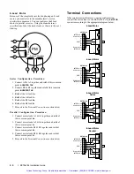
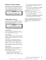
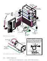
Wiring Configurations
Refer to the manufacturerÕs motor specification document
to determine the motorÕs wiring configuration. You can
also determine the wiring configuration with an ohmmeter
using the procedures below (
4-Lead Motor, 6-Lead Motor,
8-Lead Motor
). Once you determine the correct motor
wiring configuration, use the terminal connection diagram,
shown at the end of this section, that applies to your
configuration.
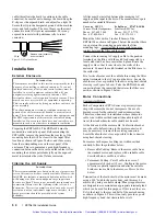
4-Lead Motor
1. Label one motor lead
A+
.
2. Connect one lead of an ohmmeter to the
A+
lead and
touch the other lead of the ohmmeter to the three
remaining motor leads until you find the lead that
creates continuity. Label this lead
AÐ
.
3. Label the two remaining leads
B+
and
BÐ
.
Verify that
there is continuity between the
B+
and
BÐ
leads
.
4. Proceed to the
Terminal Connections
section below.
6-Lead Motor
1. Determine, with an ohmmeter, which three of the six
motor leads are common (one phase).
2. Label each one of these three motor leads
A
.
3. Using the ohmmeter, verify that the remaining three
leads are common.
4. Label the remaining three leads
B
.
5. Set the ohmmeter range to the 100 ohm scale
(approximately).
6. Connect the ohmmeterÕs negative lead to one of the
motor leads labeled
A
. Alternately measure the
resistance to the two remaining motor leads also
labeled
A
. The resistance measurements will reflect
one of the following two scenarios.
Scenario #1
Ñ The resistance measurements to
the two remaining motor leads are virtually identical.
Label the two remaining motor leads
A+
and
AÐ
.
Label the motor lead connected to the negative lead
of the ohmmeter
AÊCENTER TAP
(this is the center
tap lead for Phase A of the motor).
Scenario #2
Ñ The resistance measurement to the
second of the three motor leads measures 50% of the
resistance measurement to the third of the three
motor leads. Label the second motor lead
AÊCENTER
TAP
(this is the center tap lead for Phase A of the
motor). Label the third motor lead
AÐ
. Label the
motor lead connected to the ohmmeter
A+
.
7. Repeat the procedure as outlined in step 6 for the
three leads labeled
B
(
BÊCENTER TAP
is the center
tap lead for Phase B of the motor).
8. Proceed to the
Terminal Connections
section below.
Artisan Technology Group - Quality Instrumentation ... Guaranteed | (888) 88-SOURCE | www.artisantg.com
Summary of Contents for Compumotor ZETA6104
Page 45: ...Artisan Technology Group Quality Instrumentation Guaranteed 888 88 SOURCE www artisantg com...
Page 49: ...Artisan Technology Group Quality Instrumentation Guaranteed 888 88 SOURCE www artisantg com...
Page 53: ...Artisan Technology Group Quality Instrumentation Guaranteed 888 88 SOURCE www artisantg com...
Page 63: ...Artisan Technology Group Quality Instrumentation Guaranteed 888 88 SOURCE www artisantg com...


