


Change Summary
ZETA6104 Installation Guide
R e v B
September 1997
The following is a summary of the primary technical changes to this document.
This book, p/n 88-014782-
02B
, supersedes 88-014782-
02A
and 88-014782-
01B
.
Revision B Change
Wiring diagrams (series/parallel connections) for RSxxx-xxNPS and RSxxx-xxC10 motor
options have been corrected Ð see page 9.
Revision A Changes (from 88-014782-01 B)
Topic
Description
New Hardware Revision
These are the primary changes resulting from hardware enhancements:
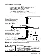
¥ New input circuit design for
P-CUT
,
HOM
,
NEG
,
POS
,
TRG-A
and
TRG-B
. To power these
inputs, you must now connect 5-24VDC (from an on-board
or
external source) to the new
V_I/O
terminal on the
I/O
connector. If
V_I/O
is connected to
+5V
,
AUX-P
can be connected
to a supply of up to +24V; if
V_I/O
is connected to an ex24V supply,
AUX-P
must
also be connected to +24V (or to
GND
). Switching levels depend on the power applied to
V_I/O
(
£
1/3 of
V_I/O
voltage = low,
³
2/3 of
V_I/O
voltage = high).
¥ Jumper JU7 was added to the ZETA6104 PCA. The purpose of JU7 is to select either
4-wire or 2-wire RS-485 communication. The default is 4-wire (JU7 in position 3).
¥ A new chip is used for the programmable output circuit (UDK2559).
New CE-marked OS Series
and RS Series Motors
This manual has been updated with data to support the new CE-marked OS Series and RS
Series motors that may be ordered with your ZETA6104 system.
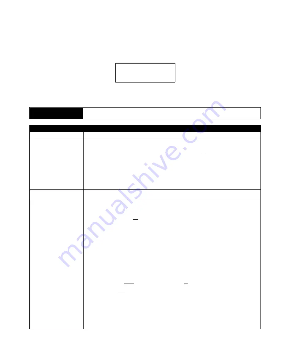
Miscellaneous Corrections
and Clarifications
Corrections:
¥ Operating temperature range is 32-113
°
F (0-45
°
C);
previously documented as 32-122
°
F (0-50
°
C).
¥ The ZETA6104 does
not
support RS-422 communication as noted in the previous rev.
¥ The Static Torque specs for the ZETA motors were incorrect. The
DMTSTT
(static torque)
command setting for the ZETA57-83 motor should be
DMTSTT2
(not
DMTSTT1
).
¥ The parallel motor wiring diagrams (see back cover and page 9) were in error and have
now been corrected.
¥ The encoder test procedure on page 21 was corrected.
¥ The motor inductance requirements for non-Compumotor motors (see page 43) is:
recommended range = 5.0 to 50.0 mH; minimum = 0.5 mH; maximum = 80.0 mH.
Clarifications:
¥ All inputs and outputs are optically isolated from the internal microprocessor (not from the
other inputs and outputs).
¥ The programmable outputs (including
OUT-A
) will sink up to 300mA, or source up to 5mA at
5-24VDC.
¥ You must select
either
the on-board +5V terminal
or
an external 5-24VDC power supply to
power the
AUX-P
,
IN-P
or
OUT-P
pull-up resistors. Connecting
AUX-P
,
IN-P
or
OUT-P
to the
+5V
terminal
and
to an external supply will
damage the ZETA6104
.
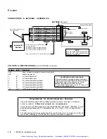
¥ If you are using an RS-232 connection between the host computer and the master
ZETA6104 connected to multiple ZETA6104s in an RS-485 multi-drop, make sure the
master ZETA6104 has these settings executed in the order given (you should place these
settings in your power-up
STARTP
program):
PORT1
(select RS-232 port, COM1, for configuration)
ECHO3
(echo to both COM ports)
PORT2
(select RS-485 port, COM2, for configuration)
ECHO2
(echo to the other COM port, COM1)
Continued . . .
Artisan Technology Group - Quality Instrumentation ... Guaranteed | (888) 88-SOURCE | www.artisantg.com
Summary of Contents for Compumotor ZETA6104
Page 45: ...Artisan Technology Group Quality Instrumentation Guaranteed 888 88 SOURCE www artisantg com...
Page 49: ...Artisan Technology Group Quality Instrumentation Guaranteed 888 88 SOURCE www artisantg com...
Page 53: ...Artisan Technology Group Quality Instrumentation Guaranteed 888 88 SOURCE www artisantg com...
Page 63: ...Artisan Technology Group Quality Instrumentation Guaranteed 888 88 SOURCE www artisantg com...


