Parker Compumotor ZETA6104 Installation Manual Download Page 41

3 4

z

  ZETA6104 Installation Guide

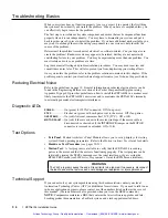
Troubleshooting Basics

When your system does not function properly (or as you expect it to operate), the first thing
that you must do is identify and isolate the problem.  When you have accomplished this, you
can effectively begin to resolve the problem.

The first step is to isolate each system component and ensure that each component functions
properly when it is run independently.  You may have to dismantle your system and put it
back together piece by piece to detect the problem.  If you have additional units available, you
may want to exchange them with existing components in your system to help identify the
source of the problem.

Determine if the problem is mechanical, electrical, or software-related.  Can you repeat or re-
create the problem?  Random events may appear to be related, but they are not necessarily
contributing factors to your problem.  You may be experiencing more than one problem.  You
must isolate and solve one problem at a time.

Log (document) all testing and problem isolation procedures.  You may need to review and
consult these notes later.  This will also prevent you from duplicating your testing efforts.

Once you isolate the problem, refer to the problem solutions contained in this chapter.  If the
problem persists, contact your local technical support resource (see 

Technical Support

 below).

Reducing Electrical Noise

Refer to the guidelines on page 19.  General information on reducing electrical noise can be
found in the Engineering Reference section of the Parker Compumotor/Digiplan catalog.
Appendix D (page 49) provides guidelines on how to install the ZETA6104 in a manner most
likely to minimize the ZETA6104Õs emissions and to maximize the ZETA6104Õs immunity
to externally generated electromagnetic interference.
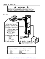
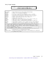
Diagnostic LEDs

POWER

.............


On (green) if 120VAC connected.  Off if no power.

STEP

.................


Flashes on (green) with each pulse sent to the motor.  Off if no pulses.

OVER TEMP

........


On (red) if internal sensor reaches 131

°

F (55

°

C).  Off = O.K.

MOTOR FAULT

....


On (red) if there is a short in the motor windings, if the motor cable is
disconnected or shorted, or if the INTERLOCK jumper on the MOTOR
connector is removed or extended.  Off = O.K.
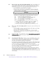
Test Options

¥

Test Panel

.  Motion ArchitectÕs Panel Module allows you to set up displays for testing

system I/O and operating parameters.  Refer to the 

Motion Architect User Guide

 for details.

¥

Hardware Test Procedure

 (see pages 20-21).

¥

Motion Test

.  A test program is available to verify that the ZETA6104 is sending

pulses to the motor and that the motor is functioning properly.  The test program can be
initiated by issuing the 

TEST

 command over the serial interface, or by accessing the

RP240 

TEST

 menu (see 

6000 Series ProgrammerÕs Guide

 for RP240 menu structure).

WARNING

The 

TEST

 program causes the end-of-travel limits to be ignored. If necessary, disconnect

the load to ensure the test moves do not damage your equipment or injure personnel.

Technical Support

If you cannot solve your system problems using this documentation, contact your local
Automation Technology Center (ATC) or distributor for assistance.  If you need to talk to our
in-house application engineers, please contact us at the numbers listed on the inside cover of
this manual.  (These numbers are also provided when you issue the 

HELP

 command.)

NOTE

: Compumotor maintains a BBS that contains the latest software upgrades and late-

breaking product documentation, a FaxBack system, and a tech support email address.

Artisan Technology Group - Quality Instrumentation ... Guaranteed | (888) 88-SOURCE | www.artisantg.com

Summary of Contents for Compumotor ZETA6104

Page 1: ...nderutilized and idle equipment along with credit for buybacks and trade ins Custom engineering so your equipment works exactly as you specify Critical and expedited services Leasing Rentals Demos In...

Page 2: ...RLOCK POW ER STEP OVER TEMP OVER TEMP MOTOR FAULT MOTOR FAULT 6104 IN DEXER DRIV E ZETA Rx Tx GND SHLD 5V GND Rx Tx SHLD Rx Rx Tx Tx GND SHLD GND Z Z B B A A 5V GND HOM NEG POS TRG A TRG B OUT A GND P...

Page 3: ...y to personnel North America and Asia Compumotor Division of Parker Hannifin 5500 Business Park Drive Rohnert Park CA 94928 Telephone 800 358 9070 or 707 584 7558 Fax 707 584 3793 FaxBack 800 936 6939...

Page 4: ...ions Operating temperature range is 32 113 F 0 45 C previously documented as 32 122 F 0 50 C The ZETA6104 does not support RS 422 communication as noted in the previous rev The Static Torque specs for...

Page 5: ...on instructions provided in Appendix C If you do not follow these instructions the protection of the ZETA6104 may be impaired The ZETA6104 is sold as a complex component to professional assemblers As...

Page 6: ...rial Communication Problems 36 Product Return Procedure 37 Appendix A Resonance Ringing Damping 39 Appendix B Using Non Compumotor Motors 43 Appendix C LVD Installation Instructions 47 Appendix D EMC...

Page 7: ...l installation instructions provided in Appendix C If you do not follow these instructions the protection of the ZETA6104 may be impaired The ZETA6104 is sold as a complex component to professional as...

Page 8: ...ting the installation Matching the motor to the ZETA6104 Motor mounting and coupling guidelines Using the damping features to optimize performance Preparing for what to do next To install the ZETA6104...

Page 9: ...echanical components Therefore you should test your system for safety under all potential conditions Failure to do so can result in damage to equipment and or serious injury to personnel Always remove...

Page 10: ...rent or connect IN P to GND to sink current IN P can handle 0 24V with max current of 100 mA Voltage range 0 24V Outputs All outputs are optically isolated from the microprocessor not from the other o...

Page 11: ...n off off 28 on on on off on 29 on on on on off 30 on on on on on 31 Factory Settings If you ordered a ZETA Series motor as part of your ZETA6104 system e g ZETA6104 83 62 then the DIP switches will b...

Page 12: ...as Resistor 681 W NOTE Set the switches to ON as illustrated to use the internal resistors Do this for a single unit or for the last unit in a multi drop only If these resistor values are not appropri...

Page 13: ...ercise the motor matching procedures on page 22 you will need to access the potentiometers at the top of the ZETA6104 chassis The motor matching procedures are placed after the Electrical Connections...

Page 14: ...an external supply of up to 24V but do not use both the on board 5V terminal and an external 5 24V supply If V_I O is connected to a 5V supply on board or external AUX P can be connected to a supply...

Page 15: ...tep 3 Recalculate the equivalent resistance of RC Ra Rd Rc Ra Rd 120W 720W 720W 110 77W Since the equivalent resistance is close within 10 to the characteristic impedance of the cable Zo no further ad...

Page 16: ...ield connection to the motor case is for EMI purposes the C10 cable kit provides hardware for the shield connection C10 cable assembly instructions are provided in the C10 cable kit Auto Current Stand...

Page 17: ...48 0 10 20 30 40 50 RS31B Speed RPS 0 Torque 40 80 120 160 200 oz in 0 28 0 56 0 84 1 12 1 40 N m Power watts hp Series 120 0 16 Parallel 230 0 31 0 10 20 30 40 50 Speed RPS 0 Torque 40 80 120 160 200...

Page 18: ...ture is enabled with the HOMZ1 command Chassis Ground GND HOM NEG POS Iso Ground SHLD GND Z Z B B A A 5V I O Connector LIMITS Connector ENCODER Connector 5V connected to AUX P and V_I O sourcing curre...

Page 19: ...ground earth Isolated logic ground Z Channel signal input Z Channel signal input B Channel quadrature signal input B Channel quadrature signal input A Channel quadrature signal input A Channel quadrat...

Page 20: ...N P AUX P V_I O Electronic Device Out 5 24 Volts Output Ground The output should be able to sink at least 1mA of current ZETA6104 I O Connector see schematic drawing above Pulled up to 5V sourcing TRG...

Page 21: ...both Outputs including OUT A 4 7 KW Output Connection Ground Connection 5VDC OUT P 5V GND ZETA6104 ISO GND ISO GND External 5 24VDC Supply an alternative to using the on board 5V terminal Pull up Conn...

Page 22: ...PROGRAMMING TIP Connecting to a sinking output Set the input s active level to low with the INLVL command active low Connecting to a sourcing output Set the input s active level to high with the INLVL...

Page 23: ...ISO GND Sourcing Input Sinking Input open collector UDK2559 open collector UDK2559 Connection to an Inductive Load active low Output Connection OUT P 5V GND ZETA6104 4 7 KW 5VDC ISO GND External Supp...

Page 24: ...1 2 3 4 5 6 7 8 5 GND I5 I4 I3 I2 I1 O5 O4 O3 O2 O1 TM8 Thumbwheel Module ZETA6104 Connection to your own Thumbwheel Module Sign Bit Thumbwheel 1 Thumbwheel 2 Thumbwheel 3 Thumbwheel 4 Thumbwheel 5 T...

Page 25: ...57 193 272 408 ZETA83 135P 4 00 24 8 65 355 445 667 Compumotor ZETA AC POWER Power Cable Provided in ship kit p n 44 014768 01 Length 6 6 ft 2 0 m 95 132 VAC 50 60 Hz 6104 INDEXER DRIVE POWER STEP OVE...

Page 26: ...ncing noise problems try adding resistors to reduce noise sensitivity see illustration below Long Shielded Cable Add a resistor between the input and the power supply this will lower the input impedan...

Page 27: ...ming tools Using Motion Architect 1 To install insert Disk 1 into your disk drive and run the Setup program setup exe 2 After the Setup program is finished click on Run Motion Architect 3 From the Pro...

Page 28: ...sition 4000 Enter the ENC command to return the ZETA6104 to the default motor step mode TPM response motor counts TPE response encoder counts Direction of rotation Counter clockwise negative counts Cl...

Page 29: ...e time You should perform this procedure with the motor not coupled to the load because the characteristics you are matching are those only of the drive motor combination Apply AC power when necessary...

Page 30: ...tly until you find the resonance point Step 6 Adjust the balance pot until you find the setting that provides minimum motor vibration and smoothest operation Step 7 Repeat steps 3 6 Step 8 Run the mot...

Page 31: ...ngineer should check the machine design to ensure that the mounting structure is adequate Motor Dimensions xxxx denotes millimeters 1 856 47 14 2 27 57 66 max 1 502 1 498 38 15 38 05 120 0 215 0 195 5...

Page 32: ...hrough the face flange and dissipated in the thermal mass You can also use a fan to blow air across the motor for increased cooling if you do not get enough cooling by conduction through the face flan...

Page 33: ...ic Viscosity procedure below For a theoretical discussion about these three circuits and how they minimize resonance and ringing refer to Appendix A NOTE You need to match the motor to the ZETA6104 be...

Page 34: ...TIND4 1 42 2 33 201 330 DMTSTT3 RS33B S 5 03 10 30 DMTIND3 2 34 3 48 331 492 DMTSTT4 RS33B P less than 5 02 DMTIND4 2 34 3 48 331 492 DMTSTT4 S Series Connection P Parallel Connection Factory default...

Page 35: ...a move that is representative of your application Use the same motion parameters that you set up in step 4 If you have not changed these settings simply issue the GO command Step 6 Increase the settin...

Page 36: ...move 1 Issue the DELVIS command to disable active damping 2 Make a move that is representative of your application with similar velocity and acceleration The velocity must 3 rps or less in order for...

Page 37: ...s provided below For more detailed information on creating a set up program refer to the 6000 Series Programmer s Guide Command Function Factory Default Setting DACTDP Enable disable active damping Ac...

Page 38: ...nti resonance PORT1 Subsequent serial communication setup affects COM1 port DRPCHK0 COM1 to be used for 6000 language commands PORT2 Subsequent serial communication setup affects COM2 port DRPCHK1 Che...

Page 39: ...kit Motion Architect provides these features refer to the Motion Architect User Guide for detailed information System configurator and code generator Automatically generate controller code for basic s...

Page 40: ...g basics Reducing electrical noise Diagnostic LEDs Test options Technical support Solutions to common problems Resolving serial communication problems Product return procedure Artisan Technology Group...

Page 41: ...104 s emissions and to maximize the ZETA6104 s immunity to externally generated electromagnetic interference Diagnostic LEDs POWER On green if 120VAC connected Off if no power STEP Flashes on green wi...

Page 42: ...not grounded 4 Drive fault detected 5 Undervoltage AC supply 95 VAC 6 Improper wiring 7 Load is jammed 8 No torque from motor 1 See Diagnostic LEDs above 2 a Move load off of limits or disable limits...

Page 43: ...blem Remedy based on the possible causes No Response COM port not enabled for 6000 language communication If RS 232 connected to COM 1 issue PORT1 and DRPCHK commands If RS 232 connected to COM 2 issu...

Page 44: ...over repair costs in the event the unit is determined by the manufacturers to be out of warranty Step 2 Before you return the unit have someone from your organization with a technical understanding of...

Page 45: ...Artisan Technology Group Quality Instrumentation Guaranteed 888 88 SOURCE www artisantg com...

Page 46: ...hows a typical case as motor speed increases resonances of varying levels occur Usually the motor can accelerate through the resonance point and run smoothly at a higher speed However if the resonance...

Page 47: ...ELVIS command to enable electronic viscosity and optimize it for a specific application see procedure on page 29 The first two damping circuits anti resonance and active damping work at speeds greater...

Page 48: ...ng oscillations and lasts a very brief time Electronic Viscosity EV The ZETA6104 uses closed loop current control to develop and maintain precise currents in the motor phases When EV is off the curren...

Page 49: ...Artisan Technology Group Quality Instrumentation Guaranteed 888 88 SOURCE www artisantg com...

Page 50: ...nfiguration 4 Lead Motor 1 Label one motor lead A 2 Connect one lead of an ohmmeter to the A lead and touch the other lead of the ohmmeter to the three remaining motor leads until you find the lead th...

Page 51: ...l this common point A 2 Connect motor leads A2 A4 together and relabel this common point A 3 Connect motor leads B1 B3 together and relabel this common point B 4 Connect motor leads B2 B4 together and...

Page 52: ...current as a unipolar rating use the following formula to convert the unipolar current rating to the correct bipolar rating Unipolar Current 0 707 Bipolar Current After you make the conversion use the...

Page 53: ...Artisan Technology Group Quality Instrumentation Guaranteed 888 88 SOURCE www artisantg com...

Page 54: ...mer Adding Line Fuses Line fuses need to be added to protect the transformer and associated wiring If the live wire cannot be readily identified fuse both phase conductors The value of fuse required i...

Page 55: ...or or its designated repair facilities Thermal Safety The Motor May Be HOT The motor may reach high temperatures during normal operations and may remain hot after power is removed Sonic Pressure High...

Page 56: ...absorbers described in these installation recommendations are made from a low grade ferrite material which has high losses at radio frequencies They therefore act like a high impedance in this waveba...

Page 57: ...ing AC supply and the input to the drive The manufacturer s part numbers for suitable filters are Corcom 10VV1 Corcom World Headquarters Phone 847 680 7400 Fax 847 680 8169 Schaffner FN670 10 06 Schaf...

Page 58: ...ip the braid to a suitable ground metal back plane of drive mounting panel or earth point of device that receives the feedback see Figure 3 Step Motors It is preferable to use motors with screw termin...

Page 59: ...ble I O Cable I O Cable Limits Cable Encoder Comm Figure 3 EMC Connections for ZETA6104 Motor Encoder Cable Safety Earth Cable green yellow Step Motor Figure 4 EMC Connections for Step Motor P Clip Sa...

Page 60: ...9 configuration active damping 26 address 4 anti resonance 26 autobaud 4 bias resistor selection 5 COM 2 port function 5 electronic viscosity 29 inductance 27 matching the ZETA6104 to the motor 22 mot...

Page 61: ...ngs see DIP switch settings EMC guidelines 49 LVD instructions 47 mounting see mounting precautions 2 process overview 2 test 20 interlock jumper 9 34 J L jumper settings 5 LEDs diagnostic 18 34 limit...

Page 62: ...evice connecting to 16 sourcing output device connecting to 13 15 specifications motor 3 peak power requirements 18 speed torque curves 10 overall list of see also back cover speed torque curves ZETA...

Page 63: ...Artisan Technology Group Quality Instrumentation Guaranteed 888 88 SOURCE www artisantg com...

Page 64: ...ER Compumotor Rx Tx GND SHLD 5V GND Rx Tx SHLD Rx Rx Tx Tx GND SHLD GND Z Z B B A A 5V GND HOM NEG POS TRG A TRG B OUT A GND P CUT 5V OUT P IN P AUX P V_I O 1 2 49 50 95 132 VAC 50 60 HZ POWER STEP OV...

Page 65: ...uipment Have surplus equipment taking up shelf space We ll give it a new home Learn more Visit us at artisantg com for more info on price quotes drivers technical specifications manuals and documentat...

Reviews: