


Chapter 1. Installation
7
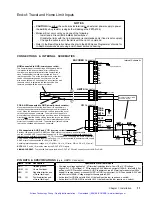
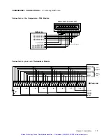
Electrical Connections
To install the ZETA6104 so that it is
LVD compliant
, refer also to the supplemental instruc-
tions in Appendix C. Appendix D provides guidelines on how to install the ZETA6104 in a
manner most likely to minimize the ZETA6104Õs emissions and to maximize the
ZETA6104Õs immunity to externally generated electromagnetic interference.
Grounding System
MOTOR
INTERLOCK
A
CENTER TAP
A+
A-
EARTH
B+
B-
B
CENTER TAP
INTERLOCK
95-132 VAC
50/60 Hz
GND
SHLD
1
49
GND
SHLD
SHLD
GND
GND
2
50
GND
COM 1
COM 2
ENCODER
LIMITS
I/O
PROGRAMMABLE I/O
GND
AC POWER
Compumotor
GND
(if COM2 is RS-485) *
Isolated
Ground
SHLD
(if COM2 is RS-232) *
EARTH
NOTE
: The inputs and outputs are isolated
from the internal microprocessor, but are not
isolated from the other inputs and outputs.
GND
(if COM2 is RS-232) *
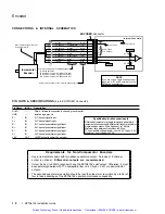
* The function of COM2Õs terminals depends
on whether it is configured for RS-232 (the
factory default configuration) or for RS-485
(see page 5 for configuration).
GND
GND
GND
GND
GND
(even number pins)
SHLD
SHLD
EARTH
Ground Pin
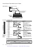
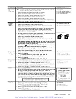
Pulse Cut-Off (P-CUT) Ñ Emergency Stop Switch
I/O Connector
+5V connected to AUX-P and V_I/O
(sourcing current).
Pr5V power to the P-CUT pull-up resistor. As an alternative, you can
connect AUX-P to an external supply of up to +24V (but do not use both the on-board +5V
terminal and an external 5-24V supply). If V_I/O is connected to a +5V supply (on-board or
external), AUX-P can be connected to a supply of up to +24V. If V_I/O is connected to an
ex24V supply, AUX-P must also be connected to +24V (or to GND).
Switching levels depend on the voltage applied to V_I/O:
LOW
£
1/3 of V_I/O voltage; HIGH
³
2/3 of V_I/O voltage
NOTE
: AUX-P and V_I/O are also used by the HOM, NEG, POS & TRG inputs.
SINKING CURRENT
: To make P-CUT (as well as HOM, NEG, POS & TRG) sink current,
connect AUX-P to GND.
TRG-A
TRG-B
OUT-A
GND
P-CUT
+5V
OUT-P
IN-P
AUX-P
V_I/O
P-CUT connected to GND
(normally-closed switch).
If this connection is opened, motion is killed and the
program in progress is terminated.
If the P-CUT input is not grounded when motion is
commanded, motion will not occur and the error message
Ò
WARNING: PULSE CUTOFF ACTIVE
Ó will be displayed in
the terminal emulator.
Internal Schematic
ISO GND
6.8 K
W
12.1 K
W
+5VDC
20.0 K
W
18.2 K
W
10.0 K
W
LM 339
30.1 K
W
CAUTION
:
You must select
either
the on-board
+5V
terminal
or
an external power supply to power the
AUX-P
pull-up resistor (for the
P-CUT
,
HOM
,
NEG
,
POS
,
TRG-A
, and
TRG-B
inputs).
Connecting
AUX-P
to the
+5V
terminal
and
an external supply will
damage the
ZETA6104
. (The same rule applies to the
IN-P
and
OUT-P
terminals, see page 14.)
Artisan Technology Group - Quality Instrumentation ... Guaranteed | (888) 88-SOURCE | www.artisantg.com
Summary of Contents for Compumotor ZETA6104
Page 45: ...Artisan Technology Group Quality Instrumentation Guaranteed 888 88 SOURCE www artisantg com...
Page 49: ...Artisan Technology Group Quality Instrumentation Guaranteed 888 88 SOURCE www artisantg com...
Page 53: ...Artisan Technology Group Quality Instrumentation Guaranteed 888 88 SOURCE www artisantg com...
Page 63: ...Artisan Technology Group Quality Instrumentation Guaranteed 888 88 SOURCE www artisantg com...


