


Chapter 1. Installation
2 3
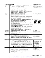
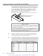
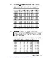
Step 3
Run your motor at the resonant speed listed in the
Offset Adjust
column. Vary the speed
slightly until you find the resonance point.
To initiate motion, type these commands (followed by a carriage return) to the ZETA6104
from the terminal emulator:
MC1
(This command makes the motion run continuously
until you issue a
!S
command
.)
V
n
(This command sets the velocity to n . For example,
V4.66
sets the velocity to 4.66 rps.)
GO
(This command initiate motion.)
To vary the speed while the motor is moving, type these
immediate
commands:
!V
n (This command selects the new velocity of n.)
!GO
(This command changes the motorÕs velocity to the new velocity value of n.)
NOTE
: To stop the motor during this procedure, issue the
!S
command.
Re-issue the
GO
command to resume motion.
Step 4
Adjust the Phase A Offset and Phase B Offset pots for minimum motor vibration and smoothest
operation. Alternate between Phase A and PhaseÊB to find the minimum vibration point.
Step 5
Run your motor at the resonant speed listed in the
Balance Adjust
column. Vary the speed
slightly until you find the resonance point.
Step 6
Adjust the balance pot until you find the setting that provides minimum motor vibration and
smoothest operation.
Step 7
Repeat steps 3Ð6.
Step 8
Run the motor at the resonant speed listed in the
Waveform Adjust
column. Vary the speed
slightly until you find the resonance point.
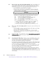
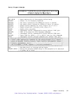
Step 9
Choose the current waveform that provides minimum motor vibrations and smoothest
operation at the speed you selected in step 8. To find the best waveform, compare motor
performance as you select different waveforms using the
!DWAVEF
command.
Waveform
DWAVEF
Setting
-4% 3rd harmonic
!DWAVEF1
¬
Factory default
-10% 3rd harmonic
!DWAVEF2
-6% 3rd harmonic
!DWAVEF3
Pure sine
!DWAVEF4
¬
Do not use if drive resolution (
DRES
) is set to 200 steps/rev
NOTE:
The
DWAVEF
command setting is NOT automatically saved in non-volatile memory; therefore, if
DWAVEF1
in not adequate, you have to place an alternative
DWAVEF
setting in a set-up (
STARTP
)
program. Refer to page 31 for an example.
Step 10
Disconnect AC power to turn off the ZETA6104. Replace the cover over the pots. This
completes the matching procedure.
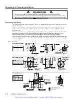
Step 11
Proceed to the next section to mount and couple the motor.
Artisan Technology Group - Quality Instrumentation ... Guaranteed | (888) 88-SOURCE | www.artisantg.com
Summary of Contents for Compumotor ZETA6104
Page 45: ...Artisan Technology Group Quality Instrumentation Guaranteed 888 88 SOURCE www artisantg com...
Page 49: ...Artisan Technology Group Quality Instrumentation Guaranteed 888 88 SOURCE www artisantg com...
Page 53: ...Artisan Technology Group Quality Instrumentation Guaranteed 888 88 SOURCE www artisantg com...
Page 63: ...Artisan Technology Group Quality Instrumentation Guaranteed 888 88 SOURCE www artisantg com...


