


Chapter 2. Troubleshooting
3 5
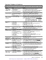
Common Problems & Solutions
NOTE:
Some software-related causes are provided because it is sometimes difficult to identify a problem as either hardware or software related.
Problem
Cause
Solution
Communication
(serial) not operative,
or receive garbled
characters
1. Improper interface connections or
communication protocol
2. COM port disabled
3. In daisy chain or multi-drop, the unit
may not be set to proper address
1. See Troubleshooting Serial Communication section below.
2.a. Enable serial communication with the
E1
command.
2.b. If using RS-485, make sure the internal jumpers are set accordingly (see
page 5). Make sure COM 2 port is enabled for sending 6000 language
commands (execute the
PORT2
and
DRPCHK¯
commands).
3. Verify DIP switch settings (see page 4), or proper use of
ADDR
command.
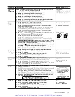
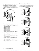
Direction is reversed.
1. Phase of step motor reversed (motor
does not move in the commanded
direction).
2. Phase of encoder reversed (reported
TPE
direction is reversed).
1. Swap the A+ and AÐ connection at the MOTOR connector.
2. Swap the A+ and AÐ connection at the ENCODER connector.
SOFTWARE ALTERNATIVE: If the motor (and the encoder if one is used) is
reversed, you can use the
CMDDIR1
command to reverse the polarity of both
the commanded direction and the polarity of the encoder feedback counts).
Distance, velocity, and
accel are incorrect as
programmed.
1. Incorrect resolution setting.
1.a. Set the drive resolution to 25,000 steps/rev (
DRES25¯¯¯
command).
1.b. Set the
ERES
command setting (default setting is 4,000 counts/rev) to
match the post-quadrature resolution of the encoder.
Compumotor encoders
:
E Series Encoders ....................................................
ERES4000
OS motor with -HJ encoder (OSxxx-xxx-HJ) ........
ERES2048
OS motor with -RE encoder (OSxxx-xxx-RE) .......
ERES4000
OS motor with -RC encoder (OSxxx-xxx-RC) ......
ERES4000
RS motor with -EC encoder (RSxxx-xxx-EC) .......
ERES4000
Encoder counts
missing.
1. Improper wiring.
2. Encoder slipping.
3. Encoder too hot.
4. Electrical noise.
5. Encoder frequency too high.
1. Check wiring.
2. Check and tighten encoder coupling.
3. Reduce encoder temperature with heatsink, thermal insulator, etc.
4.a. Shield wiring.
4.b. Use encoder with differential outputs.
5. Peak encoder frequency must be below 1.6MHz post-quadrature. Peak
frequency must account for velocity ripple.
Erratic operation.
1. Electrical noise and/or improper
shielding.
2. Improper wiring.
1.a. Reduce electrical noise or move ZETA6104 away from noise source.
1.b. Refer to Reducing Electrical Noise on page 34.
2. Check wiring for opens, shorts, & mis-wired connections.
LEDs
See Diagnostic LEDs above (page 34)
Motion does not occur.
1. Check LEDs.
2. End-of-travel limits are active.
3. P-CUT (Pulse cut-off) not grounded.
4. Drive fault detected.
5. Undervoltage (AC supply < 95 VAC)
6. Improper wiring.
7. Load is jammed.
8. No torque from motor.
1. See Diagnostic LEDs above.
2.a. Move load off of limits or disable limits with the
LH¯
command.
2.b. Set
LSPOS
to a value greater than
LSNEG
.
3. Ground the P-CUT connection.
4. Check status with
TASXF
command (see bit #4).
5. Check status with
TASXF
command (see bit #2). Check AC supply.
6. Check motor and end-of-travel limit connections.
7. Remove power and clear jam.
8. See problem: Torque, loss of.
Motor creeps at slow
velocity in encoder
mode (
ENC1
).
1. Encoder direction opposite of motor
direction.
2. Encoder connected to wrong axis.
1. Switch encoder connections A+ & A- with B+ & B-.
2. Check encoder wiring.
Programmable inputs
not working.
1. IN-P (input pull-up) not connected to a
power supply.
2. If external power supply is used, the
grounds must be connected together.
3. Improper wiring.
1.a. When inputs will be pulled down to 0V by an external device, connect IN-P
to +5V supplied
or
to an external 5-24V positive supply (
but not to both
).
1b. When inputs are pulled to 5-24V by an external device, connect IN-P to 0V.
2. Connect external power supply's ground to ZETA6104Õs ground (GND).
3. Check wiring for opens, shorts, and mis-wired connections.
Programmable outputs
not working.
1. Output connected such that it must
source current (pull to positive voltage).
2. OUT-P not connected to power source.
3. If external power supply is used, the
grounds must be connected together.
4. Improper wiring.
1. Outputs are open-collector and can only sink current -- change wiring.
2. Connect OUT-P to the +5V terminal
or
to an external supply of up to 24V.
3. Connect the external power supplyÕs ground to the ZETA6104Õs ground
(GND).
4. Check wiring for opens, shorts, and mis-wired connections.
Torque, loss of.
1. Improper wiring.
2. No power (POWER LED off).
3. Overtemp, low voltage, or motor fault.
4. Drive shutdown.
5. Current standby mode enabled
1. Check wiring to the motor, as well as other system wiring.
2. Check power connection (POWER LED should be on.
3. Check LED status (see Diagnostic LEDs above).
4. Enable drive with the
DRIVE1
command.
5. If more torque is needed at rest, disable standby mode (
DAUTOS¯
command)
Trigger, home, end-of-
travel, or P-CUT
inputs not working.
1. If external power supply is used, the
grounds must be connected together.
2. Improper wiring.
1. Connect external power supplyÕs ground to ZETA6104Õs ground (GND).
2.a. Check wiring for opens, shorts, and mis-wired connections.
2.b. When inputs are pulled down to 0V by an external device, connect AUX-P
to +5V supplied
or
to an ex5-24V supply (
but not to both
).
2.c. When inputs are pulled to 5-24V by external device, connect AUX-P to 0V.
2.d. Make sure a 5-24V power source is connected to the V_I/O terminal.
Artisan Technology Group - Quality Instrumentation ... Guaranteed | (888) 88-SOURCE | www.artisantg.com
Summary of Contents for Compumotor ZETA6104
Page 45: ...Artisan Technology Group Quality Instrumentation Guaranteed 888 88 SOURCE www artisantg com...
Page 49: ...Artisan Technology Group Quality Instrumentation Guaranteed 888 88 SOURCE www artisantg com...
Page 53: ...Artisan Technology Group Quality Instrumentation Guaranteed 888 88 SOURCE www artisantg com...
Page 63: ...Artisan Technology Group Quality Instrumentation Guaranteed 888 88 SOURCE www artisantg com...


