78
4.3 Reading the Inside LEDs
These LEDs on the electronics module can tell you a lot about the system: Are the fans are running?
Are any interlocks are open? Which lamp has failed? But you have to open the rear panel to see them.
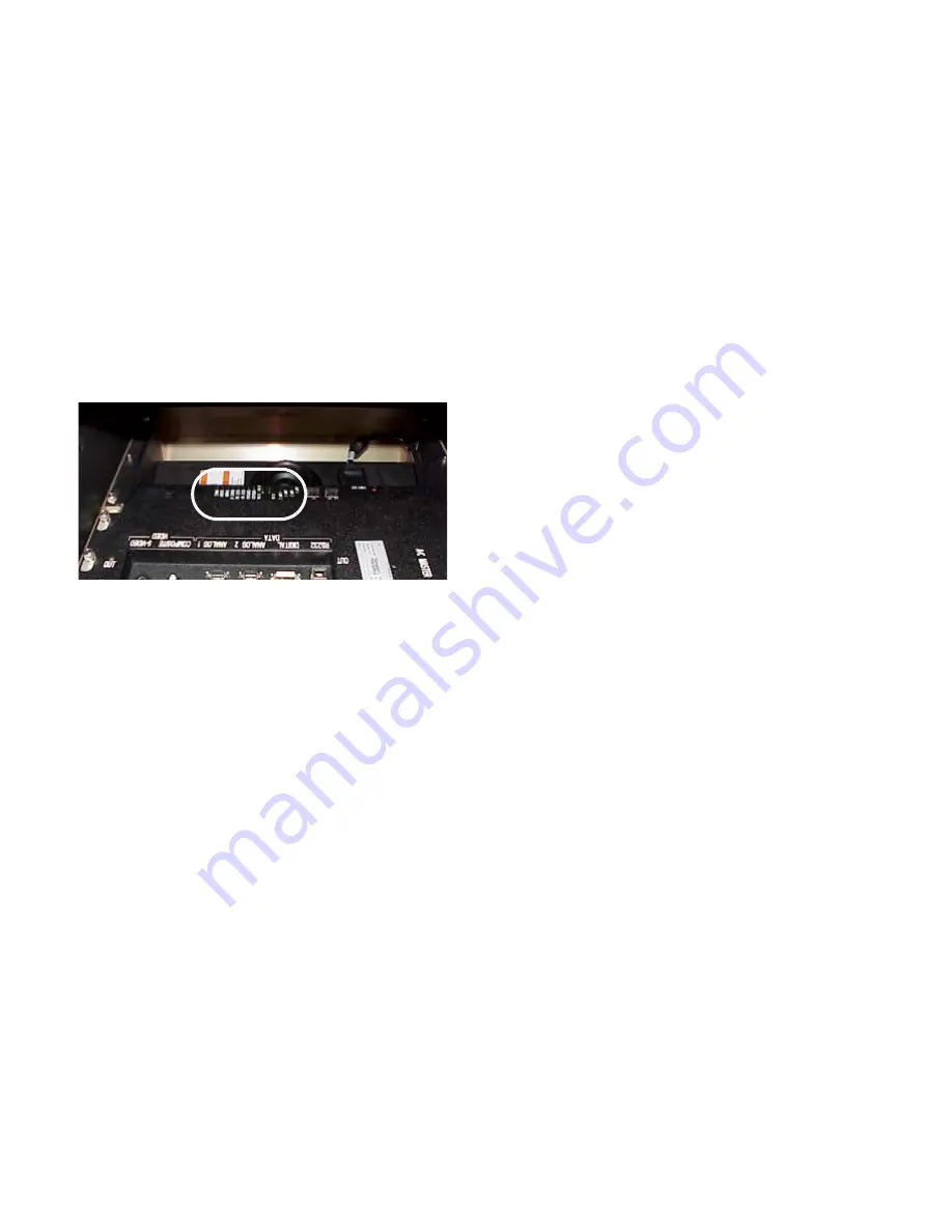
The Diagnostic LEDs are on the electronics module.
To see the Diagnostic LEDs, open the screen and
raise the cover of the center bay. Near the front
(screen side) of the electronics module you will see
the LEDs.
To see these LEDs, look from the rear of the Pan-
ther.
1. Open the rear panel of the Panther.
2. Observe the LEDs.
Lamp LEDs are arranged in the same pattern as the
lamps themselves.
• Off: The lamp is off. Lamp ballast power is not
applied, and the lamp is not on.
• Green: The lamp is on. Lamp ballast power has
been applied, and the lamp is lit (has not failed).
• Amber: The lamp is not yet on. Lamp ballast
power is applied, but the lamp is not lit. If Lamp
Control is off, this lamp may have failed.
• Red: The system tried to turn on the lamp, but
lamp would not light. Lamp ballast power is not
applied, and the lamp did not light the last time it
tried to light. The system will not try this lamp
again until AC power has been cycled off, then on
(after you have changed the lamp).
Fan LEDs indicate the fan’s state. To turn on the
lamps, all the fans must be working.
• Green: This fan is running.
• Red: This fan failed, and it caused the lamps to go
out. Lamps cannot be lit.
Standby is green when the lamps are ready to light
and the display is waiting for an ON command. It
is off when the lamps are on.
Interlock: There are two interlocks. One is a switch
which opens when the Lamp Bay door opens, and
the other is a thermal cutoff switch (not associated
with the temperature sensors). If either of these
opens, this LED turns red and the lamps will not
light. The Interlock LED will turn green when the
Lamp Bay door is closed again or the thermal cut-
off switch is reset. See Lockout below.
Lockout is red whenever the Interlock LED turns red.
As long as it is red, you cannot light the lamps.
The only way to turn off the Lockout LED is to
cycle the AC power off, then on again. When AC
power comes back, the Lockout LED will be off
provided the condition that caused the lockout has
been corrected. These events cause a Lockout con-
dition:
• Lamp Bay door opens
• Overtemp condition occurs, when Temperature
Monitoring is on
• Both lamps fail
Lockout is green for about 15 seconds after
AC power is applied and again immediately
after you turn off all lamps. Lamps cannot be
turned on during this period.
Temperature: There are four temperature sensors;
lamps, LCD, electronics module board, and Air
Intake Bay. If any of these exceed a preset limit,
this LED turns red. If it approaches close to the
limit but does not exceed it, you are warned by an
amber LED.
RS232 Data: Stays on green for one second every
time an RS232 command is received, whether or
not the command was addressed to this display.
RS232 CMD: Stays on green for one second every
time an RS232 command is received that was
addressed to this display, whether it is a global
command addressed to all displays, a specific com-
mand: for this display only, or a command meant
for a group that includes this display.
Remote IR: This LED flickers whenever IR radiation
is detected. This LED flickers very briefly, so it is
sometimes hard to see.
Power supply LED
Near the AC Master switch there is an LED
labeled ‘
BALLAST
POWER
.’ It indicates that the 370-volt
supply for the lamp ballasts is working.
Summary of Contents for PN-6730-UXP
Page 1: ...Panther PN 6730 UXP PN 6740 UXP Guide User ...
Page 2: ......
Page 3: ...i PN 6730 UXP PN 6740 UXP Panther 67 Display Unit User s Guide 070 0097 01 5 February 2003 ...
Page 6: ...iv ...
Page 9: ...vii ...
Page 10: ...viii ...
Page 15: ...5 ...
Page 16: ...6 ...
Page 23: ...13 ...
Page 25: ...15 AC Master switch AC power in ...
Page 37: ...27 ...
Page 42: ...32 ...
Page 61: ...51 ...
Page 63: ...53 ...
Page 67: ...57 ...
Page 79: ...69 ...
Page 81: ...71 ...
Page 82: ...72 ...
Page 85: ...75 ...
Page 87: ...77 Volume buttons are beneath the panel Volume up Volume down ...
Page 91: ...81 ...
Page 93: ...83 ...
Page 95: ...85 ...
Page 97: ...87 Turns on or off the User curtain immediately without showing a menu ...
Page 99: ...89 ...
Page 100: ...90 ...
Page 103: ...93 ...
Page 113: ...103 ...
Page 121: ...111 ...
Page 128: ...118 ...
Page 135: ...125 ...
Page 138: ...128 ...
Page 143: ...133 Aspect Ratiofor details see page 56 Color Temperaturefor details see page 52 ...
Page 145: ...135 Savefor details see page 66 Recallfor details see page 68 Delete for details see page 70 ...
Page 146: ...136 Misc Controlfor details see page 84 ...
Page 147: ...137 Status Monitorfor details see page 80 ...
Page 149: ...139 ...
Page 153: ...143 ...
Page 157: ...147 ...
Page 159: ...149 ...
Page 163: ...153 ...
Page 164: ...154 ...
Page 174: ...164 ...
Page 175: ...165 ...


