Settings
33
NO.
Menu contents
Set range
Increment
Default
Note
P20
FTT Voltage
-50
~
50
1
0
Fine adjustment of output voltage during
burn-back time. (The setting reflects on the
wire burning at arc end.)
Increase the set value for stronger wire
burning.
P21
BURNBACK TIME
1
※
3
-50
~
50
1
0
The time of the main welding voltage to the
back burning voltage,
Under normal circumstances, users do not
need to adjust.
P22
BURNBACK
TIME 2
※
3
-50
~
50
1
0
Burning back the role of voltage time, the user to
adjust the P22
※
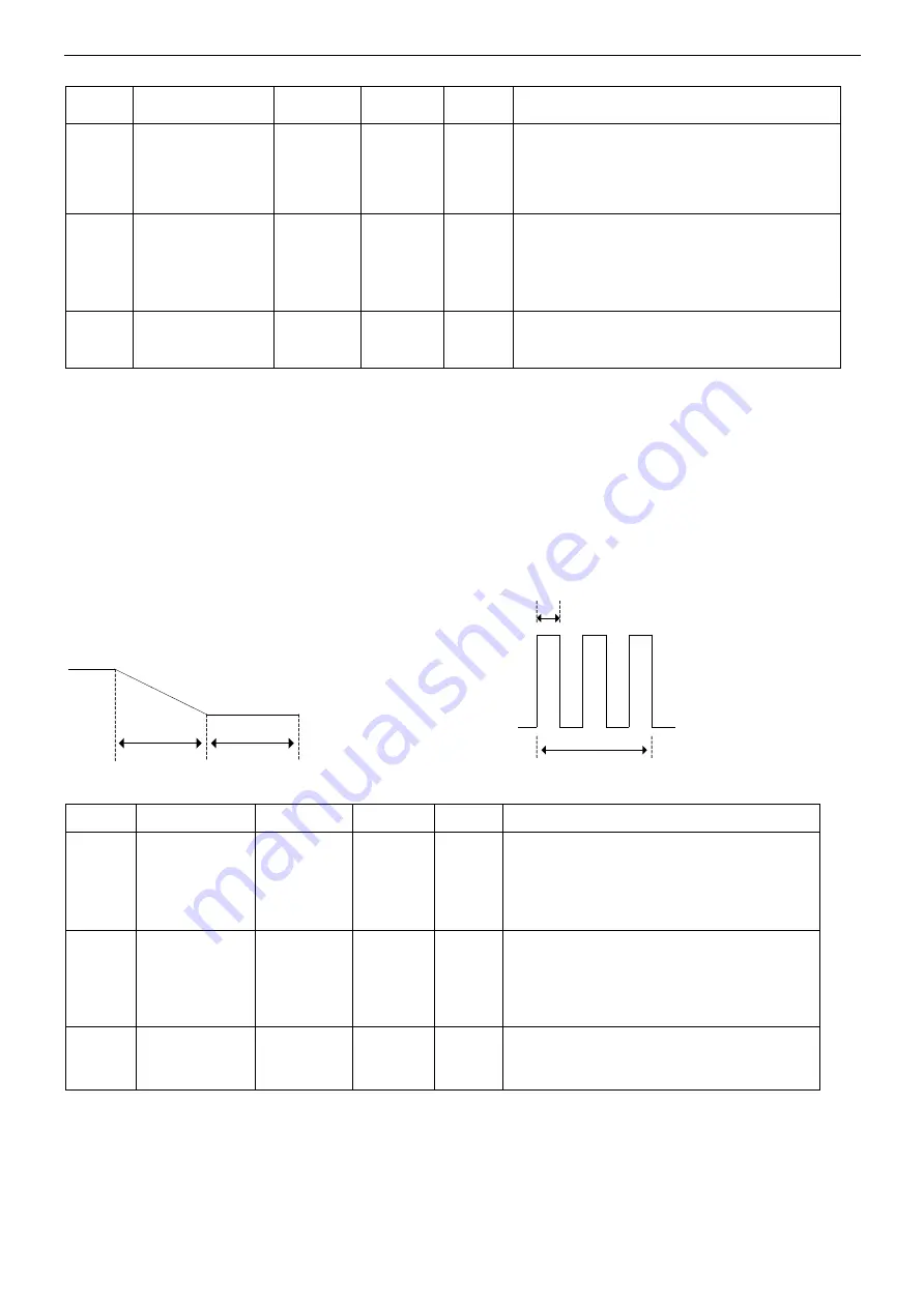
1 P00
(
SLOW DOWN
)
To obtain solid arc start, set the wire feed speed immediately after turning on the torch switch slower than that in
normal welding operation.
※
2 P12
(
Loop resistance Compute
)
When using or replacing a cable for the first time, you need to calculate the loop resistance
※
3 P21
和
P22
(
BURNBACK TIME 1 and BURNBACK TIME 2
)
It is the duration of time (short period of time) to keep supplying output voltage after stopping the arc by turning
off the torch switch. (It is to burn up excess wire fed out of the end of the torch tip
due to inertia of the wire feed motor.
【
Pulse-OFF
】
【
Pulse-ON
】
P22
P21
P21
P22
【
Special purpose machine and Robot
】
NO.
Menu contents
Set range
Increment Default
Note
P09
Wire adhesion
detection
ON/OFF
0 or 1
1
0
When the Product works with special purpose
machine or robot, the setting can be used.
When welding finishes or starts, the adhesion
between welding wire and base metal can be
detected automatically.
P23
Given current
and voltage
setting
0
、
1 or 2
1
Input signal voltage setting corresponding to
the maximum output
(when using a signal other than the remote
controller):
0: 15V input 1: 12V input 2: 10V input
P26
Robot
connection
mode
※
4
0 or 1
1
0
1: Compatible mode ("external terminal board
1" interface multiplexing);
0: Normal mode.
※
4 P26
(
Robot connection mode
)
:
When P26 is set to [1], it indicates that it is compatible with other social robots (only analog interfaces can be used with
other robots).
(Refer to Section 10.2 for details). The spare output port is used as the sticky wire detection output port. Temporary stop 1 is used as
the sticky wire detection signal given port and temporary stop 2 is used as the spinning control port. When the temporary stop 1
open between the terminals that start viscose detection, the terminal is connected between the end of that viscose detection; when the
temporary stop between the two terminals that open for spinning, the terminal is connected between the wire.
Summary of Contents for YD-500GP5
Page 11: ...Rated Specifications 7 2 4 Dimensions 机型 W H L YD 500GP5HNX 383 1240 840 ...
Page 29: ...Connection 25 ...
Page 30: ...Connection 26 ...
Page 31: ...Connection 27 ...
Page 43: ...Operation 39 9 3 CRATER Operation Turn the torch switch on and off twice ...
Page 54: ...Parts list 50 12 Parts list 12 1 Parts list for GP5 Front view Rear view Top view 20 101 ...
Page 55: ...Parts list 51 Right view Left view 35 4 26 25 8 2 6 9 7 5 26 14 10 40 59 60 61 30 106 ...
Page 56: ...Parts list 52 30 102 103 104 105 24 ...
Page 60: ...Circuit diagram 56 13Circuit diagram 13 1 Circuit diagram for YD 500GP5 ...


