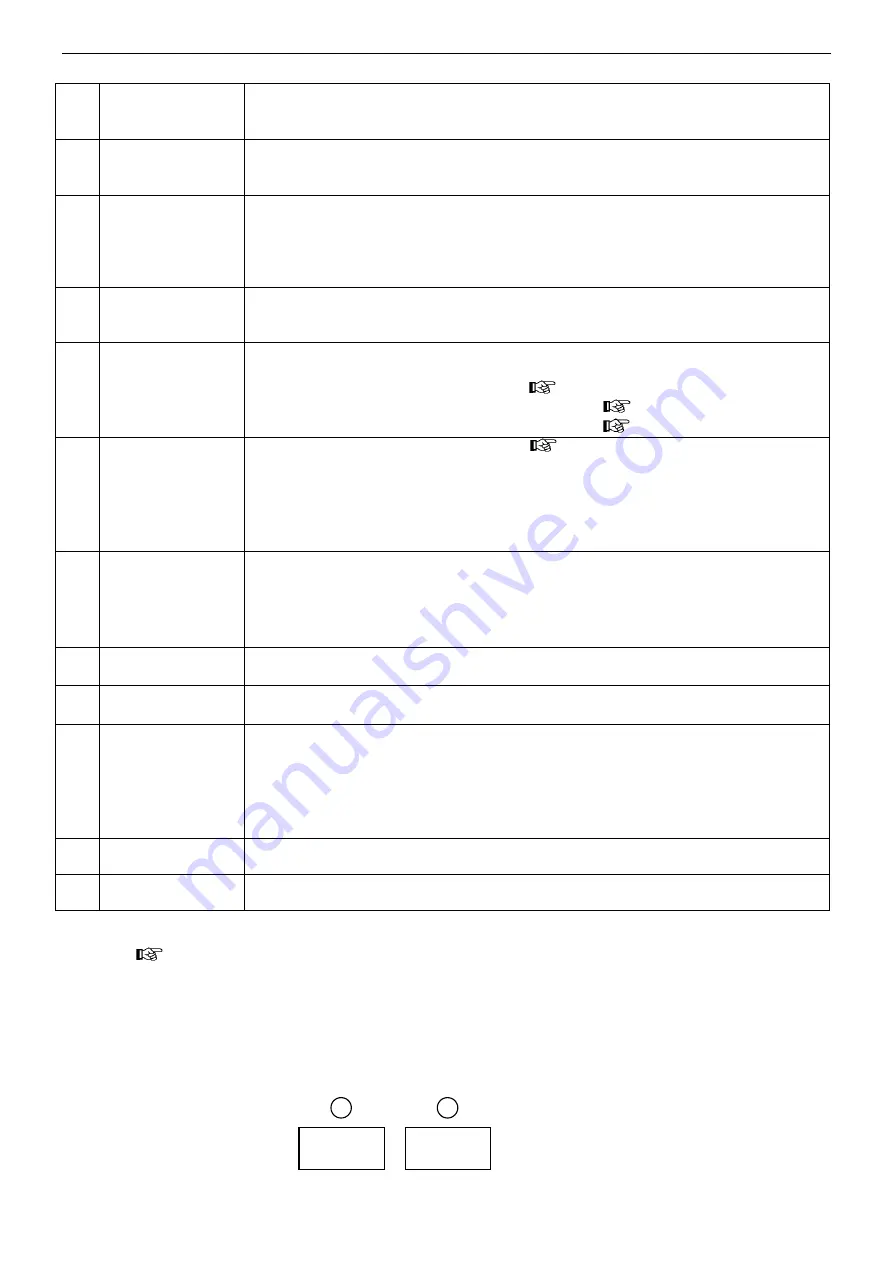
Names and functions
19
○
8
manual wire
feeding button
●
The function is used to feed welding wire into the liner before welding by holding
this key.
・
manual wire feeding speed is decided by the welding current.
○
9
switching button
●
To switch the setting among“ initial ”, “ Weld ”, “ crater ” current.
・
For crater OFF, it can not be switched. Only the setting for “ Weld ” current can be
selected.
○
10
gas check button
●
It is to check shield gas and adjust flow rate.
・
Normally, the indicator lamp is off. The lamp is on while checking gas.
・
To perform the gas check, press this button and then release, then the gas valve of
the wire feeder is turned ON and then turned OFF in 20 seconds.
Press this button once again to terminate the gas check immediately.
○
11
lock button
●
During stand-by, long press button for 1 second to lock the panel. Then all buttons
on the panel expect
○
3
○
6
○
8
○
9
○
10
can NOT be operated but the wire feeder
potentiometer can be adjusted.
○
12
mode select
button
●
Weld: welding condition setting for
○
2
~○
7
,
○
9
and
○
13
~○
17
,
○
8
○
10
for wire feeding
check, gas check for welding,
・
F. Adj: fine adjustment on F. Adj menu (
○
11
for panel lock
Section 5.4).
・
Call: To call the welding condition being recorded (
Section 5.4).
・
Record: To record the present welding conditions (
Section 5.4).
○
13
welding control
●
For welding control method selection, (
Chapter 8 )
・
crater OFF: regular welding.
・
crater ON: regular welding
~
crater welding.
・
initial ON: initial welding
~
regular welding
~
crater welding.
・
spot welding: The welding lasts certain seconds according to the spot welding time
being set. The welding stops automatically when the spot welding time is up.
○
14
welding method
●
To select the welding method
・
Standard: No pulse during welding.
・
OP1: Reserve.
・
root welding: NO pulse root welding
※
1.
・
Deepen: NO pulse deep penetration
※
1.
○
15
material
●
select the material to be welded
・
OP1 and OP2 are reserved for special design.
○
16
wire diameter
●
select welding wire diameter to be used
・
OP1 reserved for special design.
○
17
gas
●
welding method select. please prepare gas according to the requirement listed
below:
・
CO2: CO
2
gas 100%
・
MAG: Ar gas 80%
+
CO
2
gas 20%
・
MIG: Ar gas 98%
+
O
2
gas 2% or Ar gas 97.5%
+
CO
2
gas 2.5%
・
OP1, OP2, OP3 and OP4 are reserved for special design.
○
18
fuse (8A)
wire feeding motor
●
protection on the wire feeding motor
Note: be sure to turn off the power source switch before replacing the fuse.
○
19
power source
switch
●
switch the power source ON and OFF
※
1
【
Deepen
】
function is an optional software package. The test welding can last for 3 hours after setting P
menu (
Section 5.4). If you desire to continue this function, please contact the Distributor to activate the
function.
Note:
1. The welding material, welding wire diameter and welding gas being set in (
○
15
)
~
(
2
.
If there is no welding data in welding material, welding wire diameter and welding gas, it shows “--- ---”, as
shown in the picture below.
○
17
)should be in line with the
actual operational conditions.
- - -
- - -
2
5
Summary of Contents for YD-500GP5
Page 11: ...Rated Specifications 7 2 4 Dimensions 机型 W H L YD 500GP5HNX 383 1240 840 ...
Page 29: ...Connection 25 ...
Page 30: ...Connection 26 ...
Page 31: ...Connection 27 ...
Page 43: ...Operation 39 9 3 CRATER Operation Turn the torch switch on and off twice ...
Page 54: ...Parts list 50 12 Parts list 12 1 Parts list for GP5 Front view Rear view Top view 20 101 ...
Page 55: ...Parts list 51 Right view Left view 35 4 26 25 8 2 6 9 7 5 26 14 10 40 59 60 61 30 106 ...
Page 56: ...Parts list 52 30 102 103 104 105 24 ...
Page 60: ...Circuit diagram 56 13Circuit diagram 13 1 Circuit diagram for YD 500GP5 ...


