Configuration
14
●
About coolant
(
1
)
ensure to use antifreeze as coolant
Please use ethylene glycol antifreeze (other salts and alcohol antifreeze may corrode metal parts such as
welding gun and water pump).
NOTE:
When using the coolant, please use the same brand of antifreeze from the same manufacturer. It is
forbidden to mix the antifreeze from different manufacturers.
Please buy antifreeze according to the local minimum temperature. The freezing point of antifreeze should
be lower than the minimum temperature of the environment
(
2
)
In order to avoid the formation of coolant scale in the bucket, please change the coolant regularly.
Antifreeze once a year
(
3
)
When not in use for a long time, be sure to remove the coolant from the coolant tank and coolant pipe
Some components in the coolant will precipitate in the coolant pipe, which will cause the water pump not to
operate normally
Method of removing cooling liquid
The water inlet pipe joint of the welding torch is inserted into the coolant inlet of the liquid cooling system,
and the exhaust joint is inserted into the coolant outlet of the liquid cooling system
Blow the compressed air from the exhaust joint to discharge the coolant from the outlet pipe joint of the
welding gun
●
Installation and disassembly of liquid cooling system
By default, the machine is an integrated machine of welding power supply and liquid cooling system, which can
be disassembled into independent welding power supply and liquid cooling system according to needs
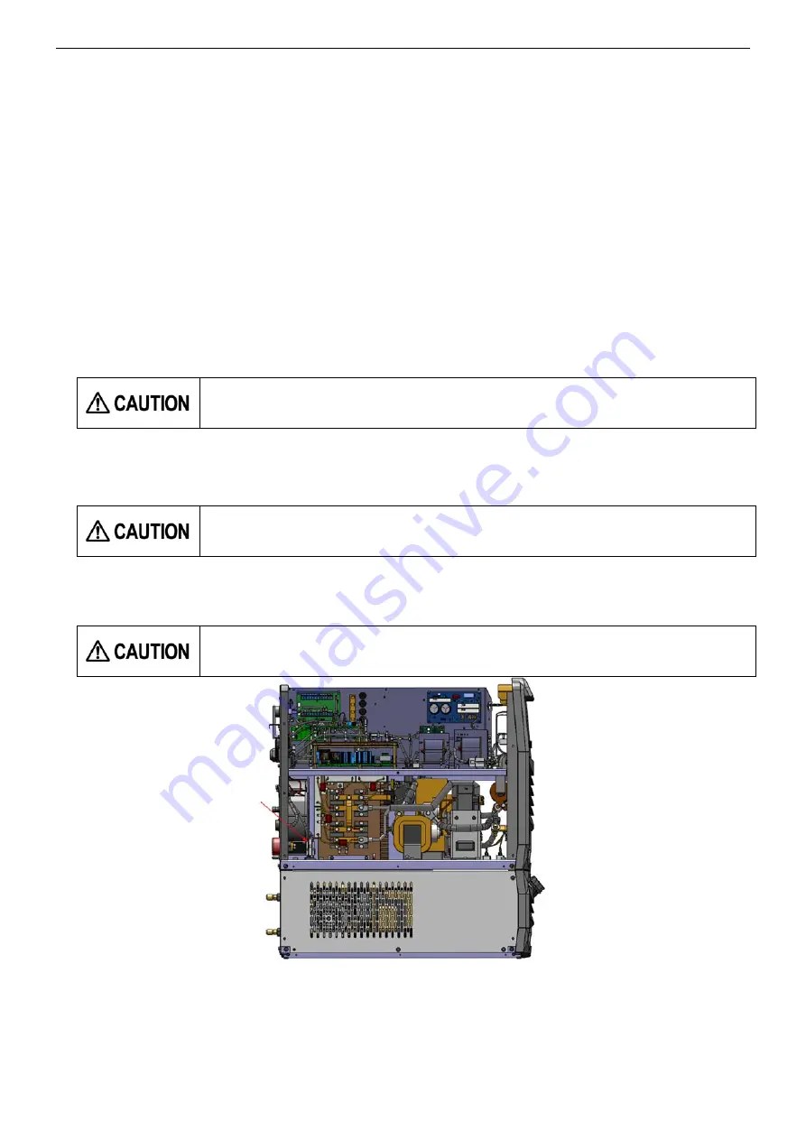
The disassembly sequence of the liquid cooling system is as follows
:
(1)Remove the welding power supply top cover and side plate (left side version), and disconnect the three
connectors as shown in the figure below
It is not allowed to drink the coolant in the coolant tank and wash the eyes with coolant
Otherwise, diarrhea and poisoning may occur.
Before the installation or disassembly of the liquid cooling system, be sure to disconnect
the welding power supply
After disassembly, there is high voltage in the 3 connectors disconnected from the
welding power supply. Please pay attention to binding and protection
Connectors (three)
Summary of Contents for YD-500GP5
Page 11: ...Rated Specifications 7 2 4 Dimensions 机型 W H L YD 500GP5HNX 383 1240 840 ...
Page 29: ...Connection 25 ...
Page 30: ...Connection 26 ...
Page 31: ...Connection 27 ...
Page 43: ...Operation 39 9 3 CRATER Operation Turn the torch switch on and off twice ...
Page 54: ...Parts list 50 12 Parts list 12 1 Parts list for GP5 Front view Rear view Top view 20 101 ...
Page 55: ...Parts list 51 Right view Left view 35 4 26 25 8 2 6 9 7 5 26 14 10 40 59 60 61 30 106 ...
Page 56: ...Parts list 52 30 102 103 104 105 24 ...
Page 60: ...Circuit diagram 56 13Circuit diagram 13 1 Circuit diagram for YD 500GP5 ...


