background image

28

Rack mounting

Install the recorder in an EIA standard rack.
Equivalent to EIA standard rack (not manufactured by Panasonic): EIA 19-inch rack type (Depth: 550 mm or more)

Note:

  •  Use four M5 x 12 screws (locally procured) to install the recorder in a rack.
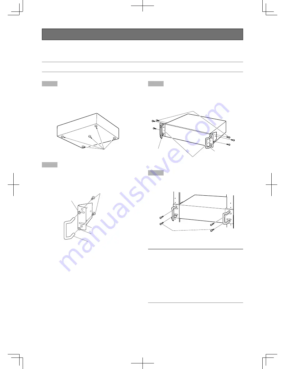


Step 1

Remove the five rubber feet from the bottom of the recorder 
using a flathead screwdriver. 
Use a screwdriver to remove the screws holding the rubber 
feet.

Step 2

Attach the rack handles to the rack mount brackets.
Fix them firmly using the screws for the rack handle (x4) and 
the washers (x4).


Step 3

Place the rack mount brackets on both sides of the recorder.
Fix them firmly with the rack mount bracket fixing screws 
(x6).

Step 4

Install the recorder in the rack.
Fix them firmly using the rack mount screws.

Important:

  •  Keep the temperature in the rack below +45 °C 


{+113 °F}.

  •  It is recommended to install cooling fans or equivalents 

to keep the temperature in the rack below +30 °C  
{+86 °F}.

  •  When installing the recorder in the rack, make a space of 

1U (44 mm {1-23/32"}) above and below the recorder 
for ventilation.

  •  Do not block the ventilation openings or slots to prevent 

the recorder from overheating.


Remove the rubber feet.

Rack handle 

Washer

Washer

Screw for rack handle

Rack mount bracket

Rack handle

Rack handle

Screw for rack mount bracket (provided)

Rack mount bracket (provided)

Rack mount screws

M5 x 12 (locally procured)

Summary of Contents for WJ-HD616/1000

Page 1: ...tion Guide Digital Disk Recorder Model No WJ HD616K WJ HD716K ERROR ALARM ALARM SUSPEND STS HDD1 A F TIMER HDD2 HDD3 OPERATE HDD4 ALARM RESET GOTO LAST GOTO DATE SEARCH COPY REV FWD SETUP SET HOLD SUB...

Page 2: ...the apparatus All work related to the installation of this product should be made by qualified service personnel or system installers The connections should comply with local electrical code CAUTION...

Page 3: ...AND LOSS INCLUDING WITHOUT LIMITATION DIRECT OR INDIRECT SPECIAL CONSEQUENTIAL OR EXEMPLARY ARISING OUT OF OR RELATING TO THE PRODUCT 2 PERSONAL INJURY OR ANY DAMAGE CAUSED BY INAPPROPRIATE USE OR NE...

Page 4: ...your outlet consult an electrician for replacement of the obsolete outlet 10 Protect the power cord from being walked on or pinched particularly at plugs convenience receptacles and the point where th...

Page 5: ...settings relating to event Event 71 Configure the common settings for event actions Common 71 Configure the event action at a terminal alarm occurrence Terminal Command 72 Configure the event action...

Page 6: ...on Network information 121 Configure the settings and operations relating to hard disk drives Disk 122 Manage the settings Settings management 123 View Log Information Logs 124 Manage hard disk drives...

Page 7: ...nisters and hard disk drives HDD fault tolerance system using the RAID function The RAID function is available as the HDD fault tolerance system when the optional RAID board WJ HD601 is installed In a...

Page 8: ...RROR TIMER STS A F HDD 1 HDD 2 HDD 3 HDD 4 OPERATE ALARM ALARM RESET ALARM SUSPEND SDHC SD memory card slot Images being captured at an alarm occurrence or at a network error can be saved on a SDHC SD...

Page 9: ...or more when using Windows XP Monitor 1 024 x 768 pixels or more 24 bit True color or better Network interface 10 100 Mbps Network interface card must be installed Web browser Windows Internet Explor...

Page 10: ...egistered trademarks of their respective owners Distributing copying disassembling reverse compiling reverse engineering and also exporting in violation of export laws of the software provided with th...

Page 11: ...se this product in a network secured by a firewall etc If this product is connected to a network that includes PCs make sure that the system is not infected by computer viruses or other malicious enti...

Page 12: ...move them just after turning the power off for around 30 seconds The lifetime of hard disk drives is limited by use Write errors may occur frequently after around 20 000 hours of operation and the hea...

Page 13: ...eo and or ii Decode AVC video that was encoded by a consumer engaged in a personal and non commercial activity and or was obtained from a video provider licensed to provide AVC video No license is gra...

Page 14: ...nded to replace them after approx 30 000 hours of operation Contact your dealer for replacement of the cooling fans Clear a space of more than 5 cm from both sides the top and the rear of this product...

Page 15: ...duct may be damaged Avoid placing receptacles that contain liquids such as water near this product If liquid spills onto this product it may cause fire or an elec tric shock Grounding Confirm that the...

Page 16: ...button Press this button to start playback Playback will be paused by pressing this button dur ing playback Lights green During playback Blinks green During pause REC button Starts manual recording R...

Page 17: ...cover data on the faulty hard disk In the RAID 6 mode When 3 or more HDD indicators light blink red it is impossible to recover data on the faulty hard disk o Monitor operation button MONITOR button P...

Page 18: ...at the center of the DVD drive and pull the disc tray gently Note After copying the recorded data on a DVD perform the procedure to eject the DVD Operating Instructions PDF Otherwise the tray may not...

Page 19: ...DVD drive cover Important When opening closing the DVD drive tray do not apply force on the tray When not using the DVD drive close the disc tray When removing the disc from the tray press the spindl...

Page 20: ...ave been already installed in these slots Up to 4 hard disk drives can be installed y RAID switch RAID Use this switch to change the operational mode of the hard disk drives Single RAID5 RAID6 Page 54...

Page 21: ...tab of the connector DVD drive cover Maintenance port cover Pull up the bottom side of cover Connection cable Connector Cable clamp Note Before disconnecting the cable be sure to turn off the power of...

Page 22: ...u Network port 10 100BASE T Connect this recorder to a network 10BASE T 100BASE TX using this port When the recorder is con nected to a network it is possible to operate the record er from a PC via a...

Page 23: ...s in the same manner as the monitor output connector BNC 7 Audio input connector 1 4 RCA pin jack AUDIO IN 1 to 4 Use this connector for LINE input A device such as a microphone amplifier can be conne...

Page 24: ...log in while the other user is already being logged in When another user tried to control a camera that is being controlled by the other user Default screen Camera channels from which live images are...

Page 25: ...a network Up to 8 hosts PCs can access the recorder concurrently When trying to log in to the recorder even though 8 hosts PCs are already accessing the recorder the host PC with the lowest priority w...

Page 26: ...is made for 10 seconds while the opera tion panel or the setup menu is displayed the mouse cursor will disappear The mouse cursor will be displayed when the mouse is moved Refer to Operating Instruct...

Page 27: ...ational mode if necessary such when using the RAID function When not installing an optional RAID board WJ HDB601 go to step 5 b Turn on the power of the recorder When using optional extension units WJ...

Page 28: ...on both sides of the recorder Fix them firmly with the rack mount bracket fixing screws x6 Step 4 Install the recorder in the rack Fix them firmly using the rack mount screws Important Keep the tempe...

Page 29: ...ded Connect the power plug of the recorder at the very end of connections When connecting combination cameras to the WJ HD616K connect them to the video input connector 1 8 coaxial con nection compati...

Page 30: ...ence in contents to be output to each monitor When connecting a monitor using a BNC cable EXT STORAGE MODE DATA RS485 CAMERA 10 100BASE T ALARM VIDEO OUT CASCADE IN ALARM CONTROL CASCADE IN MONITOR OU...

Page 31: ...audio can be heard from the connected monitor Audio can be heard only from Monitor 2 EXT STORAGE MODE DATA RS485 CAMERA 10 100BASE T ALARM VIDEO OUT CASCADE IN ALARM CONTROL CASCADE IN MONITOR OUT OU...

Page 32: ...Recorder IP address 192 168 0 250 Subnet mask 255 255 255 0 Gateway address 192 168 0 1 LAN cable locally procured 10BASE T 100BASE TX category5 straight IP address 192 168 0 x except 0 1 250 and 255...

Page 33: ...il Do not loop and bundle the cable in a circle When installing the recorder or the extension unit in the rack make a space of 1U 44 mm above and below each of them for ventilation EXT IN POWER ON OFF...

Page 34: ...ut the same audio When connecting multiple recorders in cascading connection it is impossible to output video signals of another WJ HD616K WJ HD716K from the video output connector Connect VCRs to eac...

Page 35: ...Data setup tab under the Communication page of the setup menu according to the connection Page 93 PS Data is Panasonic s proprietary protocol Contact your dealer for devices that can be connected Do n...

Page 36: ...1 Unit address controller 2 Coaxial communication unit Termination On Unit address 2 RS485 cable WV CA48 50 EXT STORAGE MODE DATA RS485 CAMERA 10 100BASE T ALARM VIDEO OUT CASCADE IN ALARM CONTROL CA...

Page 37: ...RM CONTROL CASCADE IN MONITOR OUT OUT MONITOR OUT HD AUDIO IN AUDIO OUT 3 2 1 123 4567 8 1 2 3 4 4 2 3 1 1 2 5 6 7 8 9 10 11 12 13 14 15 16 IN OUT 2 1 3 4 5 6 7 7 1 2 1 2 8 9 10 11 12 13 14 15 16 POWE...

Page 38: ...N AUDIO OUT 3 2 1 123 4567 8 1 2 3 4 4 2 3 1 1 2 5 6 7 8 9 10 11 12 13 14 15 16 IN OUT 2 1 3 4 5 6 7 7 1 2 1 2 8 9 10 11 12 13 14 15 16 POWER AC IN SIGNAL GND ON OFF OUT IN OUT CASCADE 1 2 EXT STORAGE...

Page 39: ...2 1 123 4567 8 1 2 3 4 4 2 3 1 1 2 5 6 7 8 9 10 11 12 13 14 15 16 IN OUT 2 1 3 4 5 6 7 7 1 2 1 2 8 9 10 11 12 13 14 15 16 POWER AC IN SIGNAL GND ON OFF OUT IN OUT CASCADE 1 2 EXT STORAGE MODE DATA RS4...

Page 40: ...00BASE T ALARM VIDEO OUT CASCADE IN ALARM CONTROL CASCADE IN MONITOR OUT OUT MONITOR OUT HD AUDIO IN AUDIO OUT 3 2 1 123 4567 8 1 2 3 4 4 2 3 1 1 2 5 6 7 8 9 10 11 12 13 14 15 16 IN OUT 2 1 3 4 5 6 7...

Page 41: ...IN ALARM CONTROL CASCADE IN MONITOR OUT OUT MONITOR OUT HD AUDIO IN AUDIO OUT 3 2 1 123 4567 8 1 2 3 4 4 2 3 1 1 2 5 6 7 8 9 10 11 12 13 14 15 16 IN OUT 2 1 3 4 5 6 7 7 1 2 1 2 8 9 10 11 12 13 14 15...

Page 42: ...485 port Example When connecting RS485 cameras to the video input connector 9 and 13 Mode switch No 1 and No 4 ON RS485 cable WV CA48 50 Recorder Unit number 13 Termination On Unit number 9 Terminatio...

Page 43: ...4 5 6 7 7 1 2 1 2 8 9 10 11 12 13 14 15 16 POWER AC IN SIGNAL GND ON OFF OUT IN OUT CASCADE 1 2 6 1 2 3 4 5 ON Combination camera Supporting coaxial communication 7 8 6 1 2 3 4 5 ON 7 8 6 1 2 3 4 5 O...

Page 44: ...vent recording area copy area Open collector output 24 V DC max 100 mA 16 HDD error output Signal output upon detection of an HDD error 17 Camera error output Signal output upon detection of a camera...

Page 45: ...n using multiple recorders it is possible to synchronize the switchover timing The setting for the sequence switchover timing can be configured on Sequence timing on the Monitor 1 tab or Monitor 2 tab...

Page 46: ...at 2 50 00 hour minute second pm Set at 3 00 00 pm Signal input supplied at 3 14 45 pm Set at 3 00 00 pm Signal is supplied at 3 20 00 pm Time will not be adjusted Important When Slave is selected the...

Page 47: ...ecording safely will start to shut off the power supply for the recorder After completing the internal processing a signal will be supplied from the outage processing end output terminal to the uninte...

Page 48: ...3 Alarm input 3 4 Alarm input 4 5 Alarm input 5 6 Alarm input 6 7 Alarm input 7 8 Alarm input 8 9 Alarm output 1 Alarm signal will be supplied at an event occur rence Open collector output 24 V DC ma...

Page 49: ...to the settings When an alarm device such as a buzzer a lamp etc is installed outside connect them to the alarm output terminals pin nos 9 12 23 25 of the ALARM connector or pin nos 1 9 of the ALARM...

Page 50: ...ror occurrence or until the camera is reset from the time of the error occurrence L active Error output Duration set for Buzzer starting from the time of the error occurrence L active Time adjustment...

Page 51: ...connecting RS485 cameras Set the termination switch of the RS485 port to which the RS485 camera is connected Connect to the RS485 port 1 Set the termination switch of the RS485 port 1 to On Connect t...

Page 52: ...ity by touching a steel locker etc When holding the hard disk drive hold the both sides of the hard disk drive Do not touch the circuit board or the connectors to pre vent the hard disk drive from dam...

Page 53: ...t encase the hard disk drive in the HDD canister Step 1 Fix both sides of the hard disk drive with the dedicated HDD canister using the 4 provided screws for HDD canister instal lation Tightening torq...

Page 54: ...re installed in the recorder The RAID 6 mode is operable only when 4 or more hard disk drives are installed in the recorder When using an extension unit change the operational mode after connecting it...

Page 55: ...wer of the recorder To turn off the power of the recorder during recording or playback proceed as follows During recording Step 1 Select Off for Recording on the Recording tab under the Basic page of...

Page 56: ...for further information about the basic operations of the setup menu Configure the minimum settings required to use the recorder Step 1 Hold down the SETUP ESC button for 2 seconds or more The setup m...

Page 57: ...er using the web browser the setup menu will be displayed by clicking the Setup button on the oper ation window The operation window displayed on the web browser is same as that displayed on Monitor 2...

Page 58: ...display can be configured on the Display page y Communication button Select this button to display the Communication page page 92 The settings relating to the communication with other devices such as...

Page 59: ...itor 2 Note The setup menu can also be displayed by holding down the SETUP ESC button for more than 2 seconds on the front panel of the recorder At the startup of the setup menu for the first time Qui...

Page 60: ...sired tab and click the mouse button The setup menu page of the selected tab will be dis played Operation using buttons on the front cover Step 2 Select the desired setup menu Press the SET button aft...

Page 61: ...ter moving the cursor to the desired setting or setting value Enter a value It is possible to enter a value by pressing the desired camera selection buttons 1 to 1 10 The available setting values are...

Page 62: ...ayed and it is possible to enter the characters When using a mouse it is possible to set by clicking the icon Step 5 Apply the settings to the recorder and exit the setup menu Hold down the SETUP ESC...

Page 63: ...to Resolution of the following of the setup menu Resolution under the Emergency rec tab on the Basic page Resolution of program 1 4 on the Program tab under the Schedule page Schedule Create recording...

Page 64: ...e will be applied to PROG1 to 4 image quality of all the recording modes and the recording rate on the Schedule page of the setup menu When the settings on the Schedule page of the setup menu are chan...

Page 65: ...fault English Go to last before Select the time to be skipped to when the GOTO LAST button is pressed during playback from the following 5s 10s 30s 1min 5min before the start time of the latest record...

Page 66: ...eceives a signal from the ALARM CONTROL connector and adjusts the clock Master Supplies a signal from the ALARM CONTROL connector on the rear panel to other connected devices and the devices will adju...

Page 67: ...right side of the entry field On screen keyboard for time date entry will be displayed and it is possible to enter the time date Refer to Operating Instructions PDF for further information about how t...

Page 68: ...elect On or Off to determine whether or not to record the displayed time date together as a part of the recorded image Default On Note It is possible to select On or Off to determine whether or not to...

Page 69: ...channels Assign audio in accordance with channels of the connected cameras When Off is selected audio will not be heard Default Off Note It is impossible to set the same channel for Audio 1 to Audio...

Page 70: ...g will be per formed for at least 8 seconds Continue Recording will not stop unless the ALARM RESET button on the front cover of the recorder is pressed or the ALM button in the status display area is...

Page 71: ...uzzer duration Determine whether or not to sound the buzzer at an event occurrence The following are available for buzzer sounding duration Off The buzzer will not sound 2s 5s 10s 20s 30s 1min Ext The...

Page 72: ...ng When Off is selected recording will not be performed Preset Select a preset position 1 to 256 to which the camera will move at an alarm occurrence When the preset positions of two or more cameras h...

Page 73: ...sitions at an event occurrence Other event actions will not be performed ALM Alarm Mode Performs every event action according to the settings OFF Performs only writing an event log Other event actions...

Page 74: ...ves the cameras to pre set positions at an event occurrence Other event actions will not be performed ALM Alarm Mode Performs every event action according to the settings OFF Performs only writing an...

Page 75: ...event actions will not be performed ALM Alarm Mode Performs every event action according to the settings Off Performs only writing an event log Other event actions will not be performed Configure the...

Page 76: ...ion detection will not be performed When On is selected VMD video motion detection areas can be set Up to 4 areas can be set for a camera channel for the detec tion area Details on video motion detect...

Page 77: ...button after moving the cursor to the desired start point of the detection area using the arrows button C D A B When using a mouse click the start point Settings for the video motion detection functi...

Page 78: ...elete area tab on the detection area setup page and click the Delete button of the area A to D to be deleted When using a mouse click the end point Up to 4 areas can be set by repeating Step 1 to 3 St...

Page 79: ...the resolution It is also possible to create special days apart from the normal schedule and a recording program of another day of the week can be switched to a special day s program automatically Th...

Page 80: ...n Off is selected for a specified camera channel imag es from a camera channel set to Off will not be recorded When Frame 3D On or Frame 3D Off is selected for Resolution Off 1 25ips 2 5ips 3 75ips 7...

Page 81: ...t Select On or Off to determine whether or not to perform event actions at an event occurrence Alarm message Select On or Off to determine whether or not to display the pop up window that notify of an...

Page 82: ...the desired date to be set as a special day Mode Select the day of the week to which the desired schedule is assigned Note Only the days of the week to which programs have been assigned on the Time t...

Page 83: ...e date on the upper right corner on the screen L Lower Displays the time date on the lower left cor ner on the screen R Lower Displays the time date on the lower right corner on the screen Default L U...

Page 84: ...4 split screen 4Screen C Displays images from camera channels 9 12 on a 4 split screen 4Screen D Displays images from camera channels 13 16 on a 4 split screen 4Screen WD Displays images from camera...

Page 85: ...a channels can be selected The Setup button is not dis played for multi screen display patterns for which any camera channels cannot be selected Step 3 Select the desired camera channels to display on...

Page 86: ...urther information about the sequential display Default Secret view The secret view is a function that skips camera images dis played with a single screen display on Monitor 2 when dis playing with th...

Page 87: ...the following Cam 1 to Cam 16 Displays an image from the select ed camera channel on a single screen 4Screen A 4Screen B 4Screen C 4Screen D 4Screen WD 7Screen WD 8Screen 9Screen A 9Screen B 9Screen...

Page 88: ...as Monitor 1 Refer to page 86 Live sequence Configure the sequential display settings of camera images The setup procedure is the same as Monitor 1 Refer to page 86 Sequence timing Determine how to sw...

Page 89: ...camera title Note Available characters _ space Embedded Rec Enter the camera title to be recorded together with the imag es The setting is also applied to the camera title to be displayed on Monitor 1...

Page 90: ...y on a 4 split screen Default 1 screen 1 screen live sequence Configure the settings for the sequential display when dis playing images with the sequential display on a 1 split screen When the Setup b...

Page 91: ...y may not work exactly with the set interval time for Dwell time Configure the settings relating to the cascade connection Cascade Select the Cascade tab on the Display page Page 60 The settings relat...

Page 92: ...lable for Camera 1 to 16 S When the length of cable used is shorter than 500 m 2 953 ft M When the length of cable used is longer than 500 m 1 640 ft and shorter than 900 m 2 953 ft L When the length...

Page 93: ...ion at communication will be displayed It is impossible to change the setting value Stop bit Stop bit types will be displayed It is impossible to change the setting value Retry timing When data recept...

Page 94: ...Allocate the RS485 port 1 and port 2 to camera channels When the Setup button is selected the following page will be displayed TERM Select a port to be controlled from the following for each camera ch...

Page 95: ...can be configured on this tab Time adjustment Select On or Off to determine whether or not to adjust the time according to the NTP server NTP server address Enter the NTP server address when adjustin...

Page 96: ...Active Change to Passive when sending images is diffi cult with Sequencial Image transmission by alarm Server directory Enter a directory of the server Enter up to 128 alphanumeric characters excludin...

Page 97: ...e Type User name Enter the user name to be required for the authentication Enter up to 32 alphanumeric characters excluding listed in the description of Available characters Page 96 Type Password Ente...

Page 98: ...e displayed When the Setup but ton is selected the following page will be displayed Enter the desired mail address and mail type for Address 1 Address 4 The setup procedure is the same as Address 1 Wh...

Page 99: ...a tor of the network The following numbers and the FTP port number are unavailable for the HTTP port number 20 21 23 25 42 53 67 68 69 79 105 110 123 161 162 546 547 995 10001 10002 10003 10004 10005...

Page 100: ...Full 10 Mbps full duplex 100M Half 100 Mbps half duplex 100M Full 100 Mbps full duplex Default Auto Maintenance port The setting for the maintenance port behind the front cover of the recorder is conf...

Page 101: ...egardless of the set ting for DHCP with or without using the DHCP server When Manual is selected for the DNS enter the DNS server addresses in Primary server address and Secondary server address Prima...

Page 102: ...ers page 96 Password Enter the password registered together with the user name Enter up to 32 alphanumeric characters excluding listed in the description of Available characters Enter up to 32 alphanu...

Page 103: ...ystem name in alphanumeric characters to manage this unit by the SNMP system for example No1 Enter up to 255 alphanumeric characters listed in the description of Available characters page 96 Location...

Page 104: ...the readme txt file on the CD ROM for details about the software Port number to PC Enter the addresses of the recipient PCs Default 01818 Retry Set the number of retry attempts for the transmission to...

Page 105: ...ansmission rate for data to be trans mitted from the following Unlimited 512Kbps 1 024Kbps 2Mbps 3Mbps 5Mbps 8Mbps Default Unlimited Note Regardless of the setting for Live video resolution when image...

Page 106: ...entication Select On or Off to determine whether or not to authenti cate the user Host authentication Select On or Off to determine whether or not to authenti cate the host Front panel Configure the s...

Page 107: ...recorder in case two or more users access the recorder simultaneously It is impossible to change the setting value for an administra tor 0 has been set for the administrator Default screen Select a st...

Page 108: ...se two or more users access the recorder simultaneously 1 high 16 low Default 1 Default screen Select a startup display to be displayed after login from the following Available setting values are the...

Page 109: ...e User name of the user to change or delete the user information The user information of the selected user will be dis played Note Select the Back button to return to the screen to regis ter a user St...

Page 110: ...in case two or more hosts access the recorder simultaneously 1 high 16 low Default 1 Default screen Select a startup display to be displayed after login from the following Cam 1 to 16 Displays an ima...

Page 111: ...ost IP address of the host to change or delete the host information The host information of the selected host will be dis played Note Select the Back button to return to the screen to regis ter a user...

Page 112: ...can be displayed and the settings can be configured Quick The Quick page is displayed and the settings can be configured Server The Server page is displayed and the settings can be configured Network...

Page 113: ...on the SD5Link page Page 60 The settings relating to the i VMD function of SD5 cameras such as detection areas sensitivity mode and depth can be config ured on this tab Configure the settings relating...

Page 114: ...The Area Sensitivity tab will be displayed Step 4 Set the detection areas and sensitivity for Motion det and Object det To set Motion det select the Setup button on the right side of White and Blue of...

Page 115: ...ting Step 4 to 6 Note To delete a set detection area select the Area delete tab on the setup page for camera s i VMD function and click the Delete button of the area White Blue Green Red to be deleted...

Page 116: ...an object enters the detection area and stays for the specified time Select the staying time from the following An alarm occurs when the object has been staying for more than the selected staying time...

Page 117: ...corner of each square markers Normally assuming that people go forward and backward it is possible to calculate the correct depth by drawing the larger marker for the nearer side and the smaller marke...

Page 118: ...eras to download or upload the setup data Upload button Starts uploading the setup data to the selected cameras When this button is selected the confirmation pop up win dow will be displayed When the...

Page 119: ...aintenance page Page 60 The version of the software and hardware of the recorder software versions of the extension units connected to the recorder MAC address and temperature inside the recorder etc...

Page 120: ...ion page and returns to the Disk information tab Total capacity Displays the total capacity of all recording areas and opera tion modes single mode RAID5 mode RAID6 mode of hard disk drives NML rec Di...

Page 121: ...twork information Select the Network information tab of the Maintenance page Page 60 The IP addresses and line speed settings of the network port on the rear panel and the maintenance port behind the...

Page 122: ...ormed 1 10 Default Off Event recording area If the available capacity of the event recording areas reaches a specified level a warning will be performed When Off is selected warning will not be perfor...

Page 123: ...te The following setting items will not be reset to the default or loaded HTTP port number FTP port number Network port Maintenance port DNS setting Bandwidth control Save settings on the SD Saves the...

Page 124: ...lected the following page will be displayed Up to 100 logs are saved Refer to page 140 for further information about the error logs Check the access log The time date when logged in out for the record...

Page 125: ...objects has been detected SD5Link cameras CSTY Objects has been staying for the specified time SD5Link cameras CDRT An object moves to the specified direction SD5Link cameras CTRM Camera terminal alar...

Page 126: ...e RAID 5 mode has an error correction data that recovers data when a single hard disk drive becomes faulty The RAID 6 mode has two error correction data that recovers data from other disk drives when...

Page 127: ...configu ration page to the page displayed during normal opera tion About the disk configuration page The operations relating to the hard disk drives such as checking the capacity of each recording are...

Page 128: ...will be displayed Select the Disk Information tab of the Disk Information page on the disk configuration page Refer to the Maintenance page the Disk Information tab for further information about the i...

Page 129: ...AID 5 RAID 6 mode the capaci ty of each hard disk drive is configured and formatted by the unit Hard disk drives that have already been installed or unformatted drives that are newly installed will au...

Page 130: ...K button The format starts and the message will be displayed to show the drive is being formatted When formatting is complete the result of format will be displayed Step 5 To return to the Format tab...

Page 131: ...nt recording area configure the setting for the pre event duration page 80 for the camera channel to be assigned to the pre event recording area Step 1 Select the Format button on the disk configurati...

Page 132: ...s can be created on a single hard disk drive It is impossible to select the camera channels set for existing pre event recording areas for other hard disk drives Enter the value 15 GB or greater for p...

Page 133: ...e hard disk drives from the recorder Page 53 Install the hard disk drives by following procedures of how to add the HDD unit Page 52 Note When replacing the hard disk units from the extension unit tak...

Page 134: ...drive number When the shutdown process is complete the HDD indi cator STS status on the front panel will go off Note When the shutdown process of the hard disk drive on which recording is being perfor...

Page 135: ...uching a steel locker etc When holding the hard disk drive hold the both sides of the hard disk drive Do not touch the circuit board or the connectors to prevent the hard disk drive from damaging by s...

Page 136: ...status on the front panel will light green and the hard disk drive will become recordable After the format the hard disk drive will become a normal recording area When a formatted hard disk drive is i...

Page 137: ...DD window will be displayed Step 3 Select the hard disk drive to add to the system and select the OK button When the hard disk drive on the recorder is to be added to the system Main y y indicates the...

Page 138: ...efore the following procedure remove the front cover from the recorder page 21 Operation of the extension unit Step 1 Hold down the USE button for 2 seconds or more The buzzer will start sounding The...

Page 139: ...the extension unit on which recording is being performed starts recording will continue on another HDD unit Images may sometimes not be recorded for several seconds when switching the HDD unit for re...

Page 140: ...oto col PANASONIC_ALM_OTHER_ ERR Parameter initialization error FAN warning Recorder MAIN FANy ERROR Extension unit EXTx FANy ERROR FAN Error Thermal error warning Recorder MAIN THERMAL ERROR Extensio...

Page 141: ...XTx RAID6 1 DOWN 1DOWN HDD error RAID6 2 down Recorder MAIN RAID6 2DOWN Extension unit EXTx RAID6 2 DOWN 2DOWN HDD error RAID6 3 down Recorder MAIN RAID6 3DOWN Extension unit EXTx RAID6 3 DOWN 3DOWN H...

Page 142: ...capacity HDD capacity warning Event area available capacity warning FULL EVENT HDD FULL EVT FULL HDD capacity warning Video Loss CAM VIDEO LOSS Camera error Video Loss recovery CAM xx VIDEO RECOVERED...

Page 143: ...E_ERR Other error for DDNS DDNS OTHER_ERR Synchronization with the NTP server complete NTP GET_TIME_OK Failed to resolve NTP serv er address from DNS NTP SVR_ADD_ERR Failed to adjust the time NTP SET_...

Page 144: ...tent Error log Network Log Display on Monitor 2 Output from the connector at the rear panel HTTP download failure HTTP DOWNLOAD_ ERR HTTP request invalid HTTP REQUEST_ERR Other errors for HTTP HTTP OT...

Page 145: ...2down RAID 3 DOWN only in the RAID 6 mode 3down HDD access indi cators Lights red The respective hard disk drive is faulty which can be recovered by replacing the hard disk drive In the RAID 5 mode i...

Page 146: ...HDD access indicator is lit or blinking red Refer to page 53 for how to remove the HDD unit Step 2 Install a new HDD unit to the slot from which the faulty disk is removed by referring the disk slot...

Page 147: ...or indicator lights orange temperature inside the recorder may be too high Check whether dust is collected around the ventilation open ings or not No image from the camera is displayed on Monitor 1 an...

Page 148: ...at the recorder cannot recorder display it The images or embedded characters displayed on the monitor look blurry Depending on the photographic subject or HDMI monitor that is connected images or embe...

Page 149: ...hat is caused by the cable discon nection or the camera malfunction The THERMAL indication is displayed The range of ambient operating temperature is between 5 C and 45 C 41 F 113 F However the THERMA...

Page 150: ...D1 52 The respective hard disk drive is faulty in the RAID 5 or RAID 6 mode In the RAID5 mode the indicator respective to the HDD that failed first will light red and the indicators for the other fail...

Page 151: ...Refer to a system administrator for further information 100 Are you accessing the wrong IP address Check the connection as follows ping IP address of this recorder If there is a reply from the recorde...

Page 152: ...r windows right click on the desktop and select Properties from the displayed pop up menu 2 Select Settings from Display Properties and then click the Advanced button 3 Click the Troubleshoot tab and...

Page 153: ...ector HDMI x2 8 Video output connector front 1 V p p 75 x1 RCA pin Audio Audio input connector 10 dBv 10 k unbalanced x4 RCA pin Cascade input connector 10 dBv 10 k unbalanced x 1 RCA pin Audio output...

Page 154: ...ng screw for HDD canister 24 pcs 1 The CD ROM contains the operating instructions PDFs and other manuals Built In DVD WJ HDB611 RAID Board WJ HDB601 Extension unit WJ HDE400 HDD canister WJ HDU40K SDH...

Page 155: ...155...

Page 156: ...800 528 6747 Three Panasonic Way 2H 2 Secaucus New Jersey 07094 Panasonic Canada Inc 5770 Ambler Drive Mississauga Ontario L4W 2T3 Canada 905 624 5010 http www panasonic ca Panasonic Sales Company Pa...

Reviews: