4-28
4.5 Connection With a PLC
4.5.1 Automatic Communication Settings Function
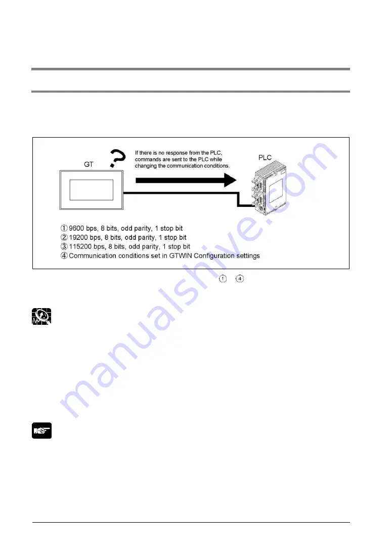
After turning on the power supply, if there is not response from the PLC connected to the GT, the GT
switches to the automatic setting mode for the communication conditions. In the automatic setting mode,
commands are sent to the PLC while changing the communication conditions in the sequence shown
below.
The GT, in automatic setting mode, continues to repeat steps
to
until there is a response from the
PLC. While it is repeating these steps, it is in the
“Standby” mode under “Configuration”
“Communication Parameters”
“Handle Communication Error” on GTWIN.
Explanation of this function:
-
Conditions when the automatic settings mode is in effect
If communication is attempted the specified number of times and there is no response from the PLC,
the GT goes into the automatic settings mode. The number of attempts is specified using the
“No. of
Retries
” parameter under “GT Configuration”
“Communication Parameters”
“Handle
Communication Error
” on GTWIN.
-
Automatically set communication conditions
In the automatic settings mode, if there is a response from the PLC, subsequent communication is
carried out under conditions matching the response. The main unit configuration settings are not
updated, however, even if the communication parameters are different from those of the main unit
configuration settings.
Note:
-
An error response from the PLC is taken as a response, and the GT does not go into the automatic
settings mode.
-
If the unit is connected to the COM port of the FP0/FP1/FP2/FP2SH/FP-M, communication between the
FP device and the PLC will not be possible if the target usage of the RS232C port has not been set to
“Computer Link”. Always set the setting on the PLC side to match “Computer Link”.
-
The automatic communication settings function cannot be used for the communication at 230400 bps
on the GT01, GT11 or GT21.
Summary of Contents for GT01
Page 25: ...Chapter 1 Features and Functions ...
Page 40: ...1 16 ...
Page 41: ...Chapter 2 Names and Functions of Parts ...
Page 42: ...2 2 2 1 Part Names 2 1 1 GT01 GT11 GT21 GT01 GT01R GT11 GT21 ...
Page 44: ...2 4 2 1 2 GT02 GT02L GT02M2 GT02G2 GT02M0 GT02M1 GT02G0 GT02G1 GT02L ...
Page 48: ...2 8 2 1 4 GT05 GT12 GT32 GT32 R GT32 E GT05 GT12 GT32 Standard High function ...
Page 49: ...2 9 GT32 R GT32 E ...
Page 62: ...2 22 ...
Page 63: ...Chapter 3 Installation and Wiring ...
Page 86: ...3 24 ...
Page 87: ...Chapter 4 Connecting with PLC ...
Page 122: ...4 36 ...
Page 123: ...Chapter 5 Troubleshooting ...
Page 141: ...Chapter 6 Specifications ...
Page 187: ...Chapter 7 Dimensions and Other Documentation ...
Page 188: ...7 2 7 1 Dimensions 7 1 1 GT01 GT01R Installation dimensions Panel cutout dimensions ...
Page 189: ...7 3 7 1 2 GT02 Installation dimensions Panel cutout dimensions ...
Page 190: ...7 4 7 1 3 GT02L Installation dimensions Panel cutout dimensions ...
Page 191: ...7 5 7 1 4 GT03M E Installation dimensions Panel cutout dimensions ...
Page 193: ...7 7 7 1 6 GT05 Installation dimensions Panel cutout dimensions ...
Page 194: ...7 8 7 1 7 GT11 Installation dimensions Panel cutout dimensions ...
Page 195: ...7 9 7 1 8 GT12 Installation dimensions Panel cutout dimensions ...
Page 196: ...7 10 7 1 9 GT21 Installation dimensions Panel cutout dimensions ...
Page 198: ...7 12 7 1 11 GT32 R GT32 E Installation dimensions Panel cutout dimensions ...
Page 200: ...7 14 7 2 4 AIGT8175 7 2 5 AIP81842 ...
Page 202: ...7 16 7 4 ASCII Code Table ...
Page 205: ......


