


Chapter 3.
22
CGA 351 User’s Manual
• Repeat the previous steps to assign the
AR-B unit type to Alarm-2.
Configuring the Alarms (cont.)
Detailed instructions for setting up the alarms are provided in Chapter 4,
Setup and Calibration. Simply follow those
instructions to program the alarm settings listed in Table 2 below.
The alarms will now respond as described in Table 64 on page 43. That is,
Alarm-1
will trip when Auto Range #2 or
Auto Range #4 is active, while
Alarm-2
will trip when Auto Range #3 or Auto Range #4 is active.
Note:
If fewer than 3 Auto Ranges are being used, Alarm 2 may be used for other purposes.
3.1.5.5
Configuring the Analog Output
In a manner similar to that used to configure the alarms in the previous section, program the
analog output with the
following settings:
Note:
Refer to Chapter 4 of the User’s Manual as required for detailed programming instructions for the analog
output.
•
unit type:
ARng
•
zero set point:
0%
•
span set point:
100%
When configured as specified above, the 4-20 mA analog output signal represents 0-100% of the currently active
Auto Range.
3.1.5.6
Switching Display Windows
After the display has been configured, the meter actually maintains multiple display windows. Although only one
window can be displayed at any given time, it is easy to switch to one of the other windows via the
User Program.
Enter the
User Program by pressing the
[ESC]
key.
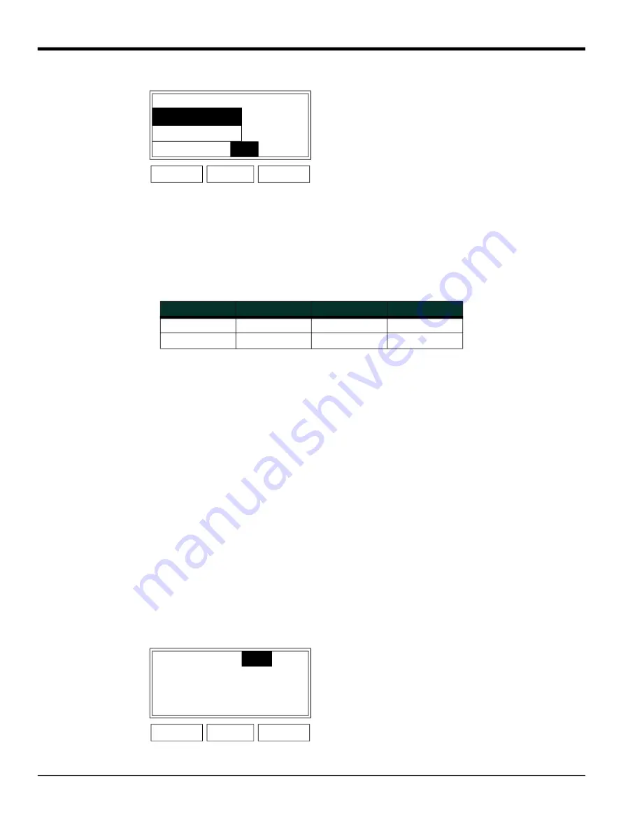
Table 15:
From 1: Cfg Ox..AR-A
Follow the instructions on
page 19 to select
Alarm-1 as
the desired output for the
AR-A unit type.
*2: Alarm-1
*2 Alarm-2
Add Remove
OK
Cancel
POWER
ESC
ENTER
Table 16: Required Alarm Settings
Alarm #
Trip Type
Trip Value
Deadband
1
Above
1.0
0.0
2
Above
1.0
0.0
Table 17:
Cfg
Cal Opt
Disp
Notice that the fourth option,
[Disp]
, is now available. Use
the [
] and [
] keys to select
[Disp]
and press
[ENTER]
.
POWER
ESC
ENTER
Summary of Contents for CGA 351
Page 2: ......
Page 4: ...Warranty 4 CGA 351 User s Manual no content intended for this page...
Page 32: ...CGA 351 User s Manual 26...
Page 94: ...CGA 351 User s Manual 88...
Page 98: ...Chapter 6 92 CGA 351 User s Manual no content intended for this page...
Page 104: ...Appendix B 98 CGA 351 User s Manual...
Page 112: ...CGA 351 User s Manual 106...
Page 118: ......