Connection
29
▐
6-7
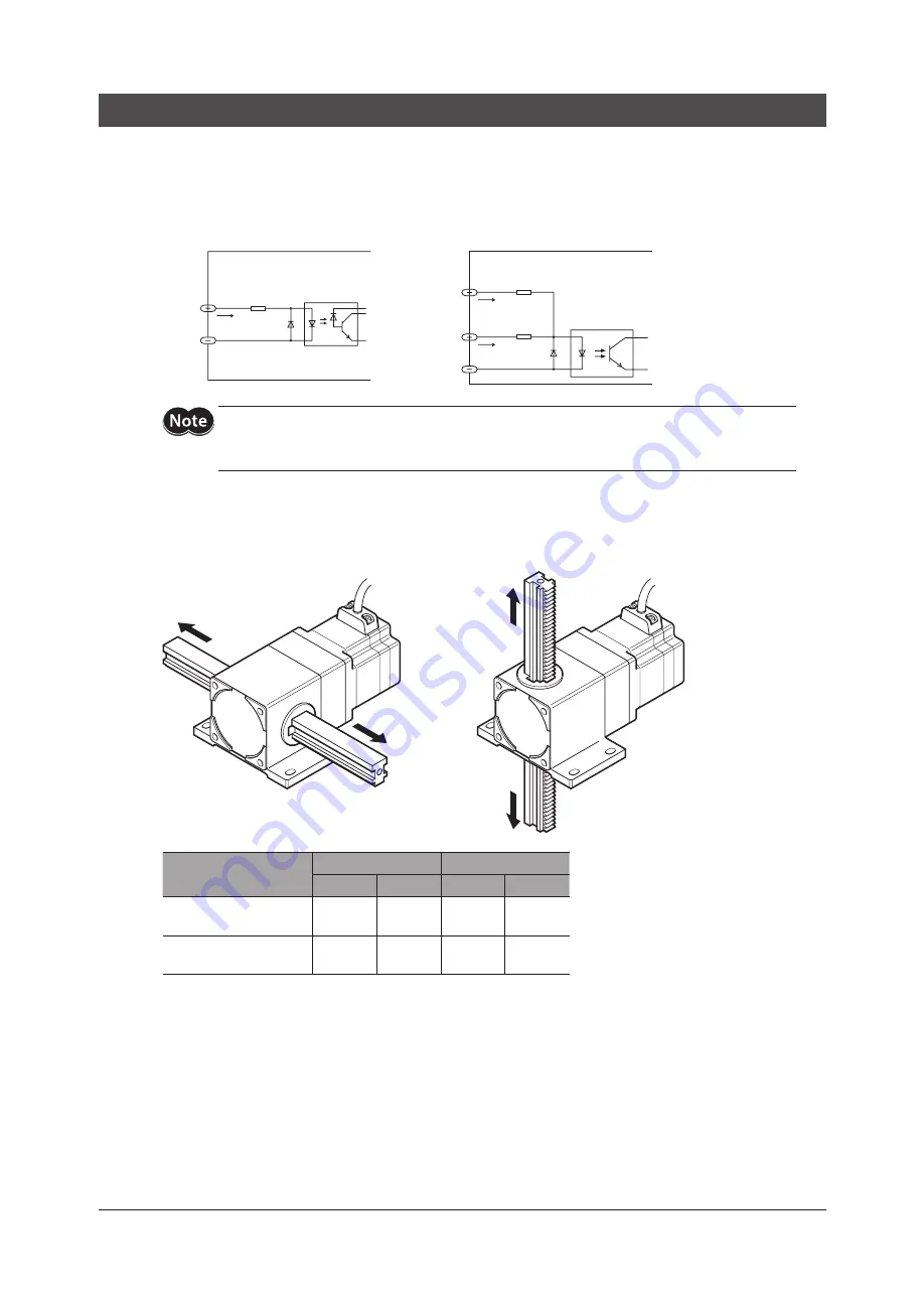
Input signals
All input signals of the driver are photocoupler inputs.
For C.OFF input, ×10 input and ACL input a signal voltage of either 5 or 24 VDC can be selected. Be sure to use it with
voltage of either 5 or 24 VDC.
The signal state represents the “ON: Carrying current” or “OFF: Not carrying current” state of the internal photocoupler
rather than the voltage level of the signal.
DIR.-A, DIR.-B
ACL, ×10, C.OFF
9, 11
10, 12
22, 32, 34
21, 31, 33
3
Driver internal circuit
Driver internal circuit
7 to 20 mA
5 mA
16 mA
4.7 kΩ
220 Ω
220 Ω
Be sure to use the same voltage for C.OFF, ×10 and ACL inputs and TIM.1/TIM.2, ASG1/ASG2 and
BSG1/BSG2 outputs. Connecting both 5 and 24 VDC power supplies may damage the driver and
power supplies.
DIR.-A input, DIR.-B input
These signals are used to move the rack. How these signals are input varies between the 2-pulse input mode and the
1-pulse input mode. Check the moving direction by referring to the figure and table below.
Left
Right
Up
Down
Lineard motor model
1-pulse input mode
2-pulse input mode
B type
F type
B type
F type
LAS2B(F)90
LAS2B(F)500
Left
Down
Right
Up
LAS4B(F)40
LAS4B(F)500
Right
Up
Left
Down
With this driver either 2-pulse input mode or 1-pulse input mode may be selected in accordance with the controller
used. Refer to p.35 for details on how to set the pulse input mode.
ALARM output is in the “OFF” state immediately after the driver power is turned on. Check to see that ALARM output
has been turned from “OFF” to “ON” before inputting pulse signals.
For the electromagnetic brake type, wait at least 0.1 second after releasing the electromagnetic brake, then input
pulse signals. When an electromagnetic brake type is used, also refer to “Operating the electromagnetic brake” on p.33.


