


31
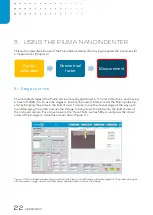
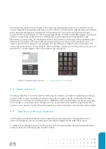
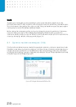
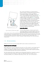
Once the parameters have been set, the scan is ini
tiated by pressing the ‘Start scan’
button. Before
continuing to a new point, including the first indentation of a matrix scan, the probe moves up to a
safe transportation height and subsequently moves to the indentation location. After reaching this
location, the find-surface procedure is initiated. Using the find-surface again for each point in a grid
scan allows the Piuma to scan samples that have a higher degree of surface topography. For very
flat samples this feature can also be switched off in the options menu (Figure 25, left).
Figure 25: Piuma matrix settings (left), defining the parameters of a matrix scan (right).
The data of the scan is saved in
a generated ‘Matrix_scan_X’
folder in the specified directory. In this
folder a file is created for each individual indentation, as well as one file containing the effective
Young’s moduli
per coordinate in a single grid.
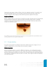
The following points should be considered when initiating a matrix scan over an area. First, since a
positive point-to-point pitch is added to the starting position, it means the first point will always be
displayed on the bottom left
in the program’s probe position field
. Because the stages move the
sample, and not the probe, it means that the indentation area will be on the bottom left of the
camera image with respect to the first point of the matrix scan. To measure another quadrant, the
pitch can be made negative.
Second, it is important to set a correct transportation height (the Z-up at X-Y move value). In case a
large point-to-point pitch is chosen, please set such a value for the transportation height so that the
probe cannot hit the sample during repositioning to a new coordinate. For large pitches and rough
samples, it is advised to set the transport height so that it is at least half the size of the point
spacing.
Summary of Contents for CHIARO NANOINDENTER
Page 1: ...PIUMA NANOINDENTER USER MANUAL ...
Page 63: ...63 Flowchart Calibration ...
Page 65: ......