background image

60

Changing the Mode

Section 3-7

3-7

Changing the Mode

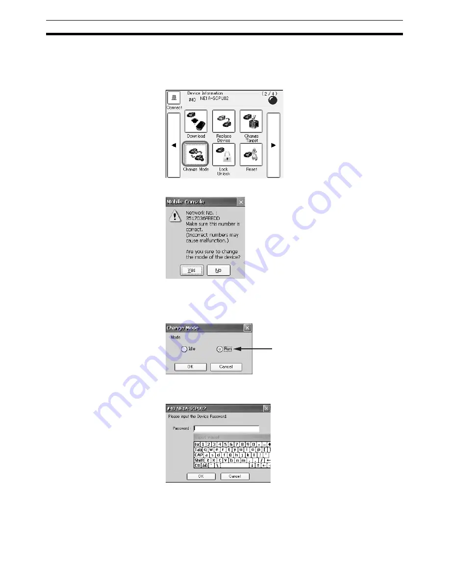
This section describes how to change the mode of the Safety Device.

1,2,3...

1.

Tap the 

Change Mode

 Icon in the Main Window (2/4).

The following dialog box will be displayed.

IMPORTANT

Always confirm that the network number is correct. Operation may not be cor-
rect if the device is configured with the wrong network number. 

2.

Check the network number and then tap the 

Yes

 Button.

3.

Select the mode and tap the 

OK

 Button.

The device password input dialog box will be displayed.

4.

Enter the password of the connected device and tap the 

OK

 Button.

After the mode is changed, the display will return to the Main Window.

Note

The mode cannot be changed for a DST1-series Controller.

The option for the current mode 
will be selected. If no option is 
selected, the current mode is 
neither Idle nor Run. 

Summary of Contents for DeviceNet Safety NE1A-HDY01

Page 1: ...OPERATION MANUAL Cat No Z921 E1 01 DeviceNet Safety NE1A HDY01 Mobile Console ...

Page 2: ...DeviceNet Safety NE1A HDY01 Mobile Console Operation Manual Produced April 2009 ...

Page 3: ...iv ...

Page 4: ...d in this manual The word Unit is also capitalized when it refers to an OMRON product regardless of whether or not it appears in the proper name of the product The abbreviation PLC means Programmable Controller Visual Aids The following headings appear in the left column of the manual to help you locate different types of information IMPORTANT Indicates important information on what to do or not t...

Page 5: ...eval system or transmitted in any form or by any means mechanical electronic photocopying recording or otherwise without the prior written permission of OMRON No patent liability is assumed with respect to the use of the information contained herein Moreover because OMRON is con stantly striving to improve its high quality products the information contained in this manual is subject to change with...

Page 6: ...tylus 11 1 5 External Connectors 12 1 6 Starting and Stopping the Mobile Console and Standby Mode 13 1 7 Using the Battery Pack 15 1 8 Using the Memory Card 19 1 9 Replacing the Clock Battery 21 1 10 Attaching the Hand Strap 23 SECTION 2 Screen Names and Console Settings 25 2 1 Screen Names and Functions 26 2 2 Console Settings 29 SECTION 3 Online Operations 37 3 1 Basic Online Operations 38 3 2 R...

Page 7: ...TENTS SECTION 4 Specifications 63 4 1 Mobile Console Ratings and Specifications 64 4 2 Battery Pack Ratings and Specifications 65 4 3 Charger Ratings and Specifications 66 4 4 Dimensions 67 Index 69 Revision History 71 ...

Page 8: ...s Controllers DeviceNet Safety System Configuration Manual Z905 This manual explains how to configure the DeviceNet Safety system using the Network Configurator DeviceNet Safety I O Terminal Operation Manual Z904 This manual describes the models specifications functions and operating procedures of the DST1 Series EtherNet IP DeviceNet Router Operation Manual Z912 This manual describes the specific...

Page 9: ...x ...

Page 10: ...AS DETERMINED THAT THE PRODUCTS WILL SUITABLY MEET THE REQUIREMENTS OF THEIR INTENDED USE OMRON DISCLAIMS ALL OTHER WARRANTIES EXPRESS OR IMPLIED LIMITATIONS OF LIABILITY OMRON SHALL NOT BE RESPONSIBLE FOR SPECIAL INDIRECT OR CONSEQUENTIAL DAMAGES LOSS OF PROFITS OR COMMERCIAL LOSS IN ANY WAY CONNECTED WITH THE PRODUCTS WHETHER SUCH CLAIM IS BASED ON CONTRACT WARRANTY NEGLIGENCE OR STRICT LIABILIT...

Page 11: ... that the uses listed may be suitable for the products Outdoor use uses involving potential chemical contamination or electrical interference or conditions or uses not described in this manual Nuclear energy control systems combustion systems railroad systems aviation systems medical equipment amusement machines vehicles safety equipment and installations subject to separate industry or government...

Page 12: ...confirm actual specifications of purchased products DIMENSIONS AND WEIGHTS Dimensions and weights are nominal and are not to be used for manufacturing purposes even when tolerances are shown PERFORMANCE DATA Performance data given in this manual is provided as a guide for the user in determining suitability and does not constitute a warranty It may represent the result of OMRON s test conditions a...

Page 13: ...xiv ...

Page 14: ...dience xvi 2 General Precautions xvi 3 Safety Precautions xviii 4 Precautions for Safe Use xx 5 Precautions for Correct Use xxi 6 Regulations and Standards xxi 7 Checking the Contents of the Package xxii 8 Definition of Terms xxii ...

Page 15: ... and equipment with double safety mechanisms This manual provides information for programming and operating the Unit Be sure to read this manual before attempting to use the Unit and keep this man ual close at hand for reference during operation WARNING Heed the following items during system configuration to ensure that safety related components are configured in a manner that allows the system fu...

Page 16: ... Principles for Design Complying with Laws and Regulations The safety devices conform to the relevant regulations and standards but make sure that they are used in compliance with local regulations and standards for the equipment or facilities in which they are applied Typical related international standards IEC 60204 Safety of Machin ery Electrical Equipment of Machines Observing Precautions for ...

Page 17: ... safety Perform a user test before operating the system and check to make sure that all the device configuration data and operations are correct After replacing a device check to make sure that the replacement device is in the appropriate configuration and is operating correctly Serious personal injury or fire may possibly occur due to rupture combustion or heat genera tion Observe the following p...

Page 18: ...k is detected stop using the Battery Pack immediately If there are flames nearby move the Battery Pack away from the flames Failure to do so may result in leaked fluid catching fire causing rupture or combustion If leaked fluid comes into contact with skin or clothing immediately rinse it thoroughly with clean water If leaked fluid comes into contact with the eyes or mouth do not rub it Flush thor...

Page 19: ...in the following locations Inappropriate and insufficient measures may result in malfunction Locations subject to static electricity or other forms of noise Locations subject to strong electromagnetic fields Locations subject to possible exposure to radioactivity Locations close to power supplies The Mobile Console is a Class A product It may cause radio interference in residential areas in which ...

Page 20: ...ch screen surface so that the screen cannot be used for inputs Do not press hard on or rub the touch screen surface Doing so may not only cause damage but may break the glass Cleaning Use a clean dry cloth for cleaning If dirt cannot be removed using a dry cloth dampen the cloth with a neutral cleaning solution wring the cloth out tightly and then wipe the dirty section Never use benzene or thinne...

Page 21: ...1 Hand strap 1 Instruction Sheet 1 SYSMAC ID registration card Japanese 1 SYSMAC ID registration card English 1 Address sheet 1 Name Description Quantity Charger RB C2001 1 Battery Pack RB B2001A 1 Power Cable Power cable for the specified destination 1 Instruction Sheet 1 Name Description Quantity Battery Pack RB B2001A 1 Instruction Sheet 1 Term Definition Mobile Console A portable terminal that...

Page 22: ...ice An input device for which special measures for use in safety controls have been implemented Emergency stop switches and safety door switches are examples of Safety Input devices Safety Output device An output device for which special measures for use in safety controls have been implemented Safety relays are an exam ple of a Safety Output device locking the configura tion device A configuratio...

Page 23: ...xxiv Definition of Terms 8 ...

Page 24: ...ontrol Keys 9 1 3 2 Power Mode Key 9 1 3 3 Character Keys 9 1 3 4 Function Keys 10 1 4 Stylus 11 1 4 1 Stylus 11 1 5 External Connectors 12 1 5 1 External Connectors 12 1 6 Starting and Stopping the Mobile Console and Standby Mode 13 1 6 1 Starting and Stopping the Mobile Console 13 1 6 2 Standby Modes 13 1 6 3 Status Indicators 14 1 7 Using the Battery Pack 15 1 7 1 Replacing the Battery Pack 15 ...

Page 25: ...le Console on the DeviceNet Safety Network Application Range of Mobile Console Devices in the following range can be maintained with the Mobile Console when it is connected to the Safety Network Controller Connectable DeviceNet Safety Devices Devices in the following series can be maintained by using the Mobile Con sole DeviceNet Safety Network to which the Safety Network Controller is connected E...

Page 26: ...t Safety Devices The Mobile Console is compatible with NE0A NE1A SCPU Safety Network Controllers as well as DST1 series Safety I O Terminals Affinity with the Network Configurator The Mobile Console uses device parameter files dvf created by the Net work Configurator Device parameter files can be downloaded to the Safety Network Controllers and Safety I O Terminals Display of Errors and Countermea...

Page 27: ...ors occur ring at the connected device will be displayed on the Maintenance Tab Page 3 2 4 Upload Uploads parameters from the connected device and saves them to the Memory Card 3 4 Device Property Displays the properties of the connected device 3 2 5 Download Device parameters copied to the Memory Card are downloaded to the connected device 3 5 Replace Device Device parameters uploaded from the co...

Page 28: ...ee levels 2 2 2 Memory Card Format This function is used to format a Memory Card 2 2 3 Date Time This function is used to set the date and time 2 2 4 Stylus This function is used to set the double tap speed and to calibrate the touch screen 2 2 5 Power Management This function is used to set the power saving features 2 2 6 Language This function is used to set the language used by the Mobile Con s...

Page 29: ...gurator ncf network configuration files File memory Memory Card only Saved in computer Changing target connection OK Target connection can be changed within same network OK Change network Select Change Connect Network from the Network Menu Parameters Upload OK by device OK Download OK by device Verification executed at the same time OK Compare OK Lock Unlock OK Verification executed at the same ti...

Page 30: ...pen for tapping the touch screen to navigate the con trols Refer to 1 4 Stylus 7 Stylus holder The stylus can be stored in the holder when it is not being used 8 Memory Card slot The Memory Card is inserted in this slot Refer to 1 8 Using the Memory Card 9 USB port The USB port is used to connect the Mobile Console to an NE0A NE1A series Safety Network Controller Refer to 1 5 1 External Connectors...

Page 31: ... cover Covers the rechargeable battery pack 2 Lock lever Locks the battery cover 3 Clock battery cover Covers the clock battery 4 Strap hooks Used to attach the hand strap 2 Lock lever 3 Clock battery cover 4 Strap hook 1 Battery cover 4 Strap hook 4 Strap hook ...

Page 32: ...haracter input modes using the NUM CHARA Key Number mode Alphabet and symbol mode Multiple characters are assigned to one key for the alphabet and symbol input mode Press the key a number of times until the desired character is dis played Power mode key Character keys Function keys Purpose Procedure To enter suspended mode Hold down the Power Mode Key To enter deep sleep mode Leave the Mobile Cons...

Page 33: ... saved to the Memory Card Use a computer to access the image files 5 jkl 5 j k l J K L 6 mno 6 m n o M N O 7 pqrs 7 p q r s P Q R S 8 tuv 8 t u v T U V 9 wxyz 9 w x y z W X Y Z 0 0 _ Key Number mode Alphabet and symbol mode Key Function ESC Escape F1 Not used F2 Not used NUM CHARA Changes the input mode Refer to 1 3 3 Character Keys TAB Tab DEL Delete Move up Move down Move right Move left OK Ente...

Page 34: ... holder on the back of the Console Note 1 Use the enclosed stylus for touch screen operations Using a sharp object may scratch the touch screen surface so that the screen cannot be used for inputs 2 Do not press hard on or rub the touch screen surface Doing so may not only cause damage but may break the glass ...

Page 35: ...move the protective cap covering the connector and connect the cable USB Communications Connector Connect the USB communications connector to the USB port of a NE1A series Controller USB version 1 1 is supported Use a commercially available USB cable IMPORTANT Make sure that the USB cable is less than 3 m LAN Connector The LAN connector cannot be used It will be used for future expansion LAN port ...

Page 36: ...nd the state of the battery 2 Refer to 2 2 6 Power Management Settings for the setting method IMPORTANT Turn OFF the power switch if the Mobile Console will not be used for a long period of time ON OFF Power switch Standby mode Description Setting method Recovery method Battery holding time See note 1 Suspended Mode The Mobile Console is held in the state it was before it was suspended It can be r...

Page 37: ...low 10 Note The times are estimates and are provided only as guidelines The actual time will depend on the operating environment and operating conditions Battery charge indicator Power status indicator Status Power status indicator Battery charge indicator Power ON Lit Lit Suspended Mode Not lit Lit Deep Sleep Mode Not lit Not lit Power OFF Not lit Not lit Battery charge indicator Battery power No...

Page 38: ...acing the Battery Pack 1 2 3 1 Turn OFF the power switch 2 Slide the lock lever on the back in the direction indicated by the arrow to unlock the battery cover 3 Lightly press the grip section of the battery cover and slide it in the direction indicated by the arrow to remove it 4 Pull out the battery stopper 5 Slide the battery pack in the direction indicated by the arrow to remove it Lock lever ...

Page 39: ...t a charged battery pack and slide it in the direction indicated by the arrow 7 Place the battery stopper firmly in place 8 Replace the battery cover 9 Slide the lock lever in the direction indicated by the arrow to lock the battery cover 2 1 1 2 ...

Page 40: ...mately 3 hours to recharge depending on the oper ating environment operating conditions and the state of the battery IMPORTANT Make sure that the temperature is between 0 and 40 C that the humidity is between 20 and 85 and that there is no condensation The battery may not charge fully in conditions outside these ranges It may also damage the battery pack IMPORTANT The capacity of the battery reduc...

Page 41: ...charge indicator is flashing red or if charging does not finish even though the specified time has been exceeded stop charging and remove the power plug from the outlet Failure to do so may occasionally result in serious per sonal injury or fire due to leakage rupture combustion or heat generation Using other devices may occasionally result in serious personal injury or fire due to leakage rupture...

Page 42: ...es of the screen captured by the print screen function of the Mobile Console Note Use the following OMRON Memory Cards HMC EF183 128 MB HMC EF283 256 MB HMC EF583 512 MB 1 8 1 Inserting the Memory Card 1 2 3 1 Pull out the slot cover for the Memory Card on the Mobile Console 2 Insert the Memory Card into the slot 3 Return the slot cover to its original position Memory Card ...

Page 43: ...3 1 Pull out the slot cover on the Mobile Console for the Memory Card 2 The eject lever will be extended if it is pressed in Press it again to eject the Memory Card 3 Pull out the Memory Card by grabbing it with your fingers 4 Close the slot cover Push Push Pull Memory Card ...

Page 44: ...ng replaced If the clock settings are lost replace the clock battery with the following procedure 1 2 3 1 Remove the stylus 2 Undo the two screws on the back of the Mobile Console using a Phillips screwdriver Screw size M2 8 3 Place your finger where the stylus is inserted and pull off the clock battery cover 4 Press the clock battery in the holder as if to insert it and then remove it Clock batte...

Page 45: ... Lithium Battery as the clock battery IMPORTANT When disposing of the battery insulate the plus and minus terminals of the battery with tape Follow all local government regulations as applicable when disposing of the battery Product specifications BR2032 Coin Type Lithium Battery Voltage 3 V Dimensions 20 0 diameter 3 2 mm thickness Recommended battery Panasonic Corporation model ...

Page 46: ...a left hand or right hand grip 1 10 1 Strap Position 1 10 2 Attaching the Strap 1 2 3 1 Thread the strap through the strap hooks for a left hand or right hand grip 2 Fold the ends of the strap over the strap hooks and secure them with the adjusters 3 Adjust the length of the strap Strap hooks Strap Strap hooks Holding in the Right Hand Holding in the Left Hand Strap Strap hooks Adjuster ...

Page 47: ...24 Attaching the Hand Strap Section 1 10 ...

Page 48: ... Screen Names and Functions 26 2 1 1 Main Window 26 2 1 2 Function Icons 27 2 2 Console Settings 29 2 2 1 Setting the Monitor Refresh Time 29 2 2 2 Adjusting the Brightness 29 2 2 3 Formatting the Memory Card 30 2 2 4 Setting the Date and Time 31 2 2 5 Setting the Stylus Properties 32 2 2 6 Power Management Settings 33 2 2 7 Language Settings 34 2 2 8 Displaying the Version Information 35 ...

Page 49: ...Device Connect Icon Tap the Connect Icon when connecting to the USB port on another device Function Menu Tap an icon to execute a function If a device is not connected online functions will be displayed in gray as shown in this example They cannot be used Device Information The node address and model of the connected DeviceNet Safety Device is displayed This information is not displayed if a devic...

Page 50: ...ur ring at the connected device will be displayed on the Mainte nance Tab Page 3 2 4 Upload Uploads parameters from the connected device and saves them to the Memory Card 3 4 Device Property Displays the properties of the connected device 3 2 5 Download Device parameters copied to the Memory Card are downloaded to the connected device 3 5 Replace Device Device parameters uploaded from the connecte...

Page 51: ...ee levels 2 2 2 Memory Card Format This function is used to format a Memory Card 2 2 3 Date Time This function is used to set the date and time 2 2 4 Stylus This function is used to set the double tap speed and to calibrate the touch screen 2 2 5 Power Manage ment This function is used to set the power saving features 2 2 6 Language This function is used to set the language used by the Mobile Cons...

Page 52: ...func tion 1 2 3 1 Tap the Monitor Settings Icon in the Main Window 3 4 The following dialog box will be displayed 2 Set the new refresh timer value and tap the OK Button The new setting will be applied and the display will return to the Main Win dow 2 2 2 Adjusting the Brightness The brightness of the screen can be adjusted to one of three levels 1 2 3 1 Tap the Brightness Icon in the Main Window ...

Page 53: ...rmatted into the Mobile Console 2 Tap the Memory Card Format Icon in the Main Window 3 4 The following dialog box will be displayed 3 After selecting the file system tap the Start Button A confirmation dialog box will be displayed 4 Tap the Yes Button Formatting will start When formatting the Memory Card has been com pleted the following dialog box will be displayed 5 Tap the OK Button The display...

Page 54: ...ore you format the Memory Card 2 2 4 Setting the Date and Time Set the current date time and time zone Make sure that the date and time settings are correct because the file names of the screen images captured by the print screen function will consist of date and time stamps 1 2 3 1 Tap the Date Time Icon in the Main Window 3 4 The following dialog box will be displayed 2 Set the current date time...

Page 55: ... Stylus Icon in the Main Window 3 4 The following dialog box will be displayed 2 Double tap the checkerboard to set the double tap speed then double tap the icon at the bottom right of the dialog box to test the settings 3 To calibrate the touch screen tap the Calibration Tab 4 Tap the Recalibrate Button and follow the instructions that are displayed on the screen ...

Page 56: ...le Time until backlight is turned OFF Time from when the backlight turns OFF until entering Suspended Mode Time from entering Suspended Mode until entering Deep Sleep Mode 1 2 3 1 Touch the Power Management Icon in the Main Window 3 4 The following dialog box will be displayed 2 Set the time until turning OFF the backlight the time from turning OFF the backlight until entering Suspended Mode and t...

Page 57: ...se or English can be selected 1 2 3 1 Tap the Language Icon in the Main Window 4 4 The following dialog box will be displayed 2 Tap the Yes Button 3 Select the desired language and tap the OK Button 4 Tap the OK Button The setting will be applied when the Mobile Console is restarted The dis play will return to the Main Window ...

Page 58: ...ying the Version Information Version information for the Mobile Console can be displayed 1 2 3 1 Tap the Version Icon in the Main Window 4 4 The version information will be displayed 2 Tap the OK Button The display will return to the Main Window ...

Page 59: ...36 Console Settings Section 2 2 ...

Page 60: ...2 Reading Device Information 42 3 2 1 Overview 42 3 2 2 Reading Parameters 43 3 2 3 Reading Device Status Alarms and Warning Information 44 3 2 4 Reading the Error History 46 3 2 5 Displaying Properties 47 3 2 6 Saving the Screen Image 48 3 3 Replacing a Device 49 3 4 Uploading Parameters 52 3 5 Downloading Parameters 54 3 5 1 Creating Device Parameter Files 54 3 5 2 Downloading the File 54 3 6 Re...

Page 61: ...has been connected online tap the Connect Icon Device Status The device status is indicated by the following colors 3 1 2 Specifying Network Numbers DeviceNet Safety supports building more than one network Even if the user system contains only one network a network number must be set For the Mobile Console to communicate with a device in the following cases the network number must be specified To ...

Page 62: ...ual network Button When the network number is acquired from the network it will be displayed as shown below 4 Tap the OK Button This completes specifying the network number The Main Window will be displayed IMPORTANT Turn ON the DeviceNet network power supply before getting the network number from the network If there is more than one network number of the same network confirm the correct number a...

Page 63: ... be displayed 3 Check the network number that is displayed 3 1 3 Changing the Connected Device This section describes how to change the connected device You can connect online to any device connected to the same DeviceNet network as the NE0A NE1A Controller to which the USB cable is connected The Mobile Console can be connected to devices that are on the same DeviceNet network as the NE0A NE1A ser...

Page 64: ...ce will be changed and the display will return to the Main Window 3 1 4 Inputting Characters Characters for file names and passwords can be entered easily by tapping the input panel with the stylus Example Save Device Parameter Dialog Box Characters can also be input using keys on the Mobile Console Device name Device node number ...

Page 65: ...2 Tap the Change Target Icon and specify the device to be monitored 3 Tap the Monitor Device Status Error History or Device Property Icon to read the device information Note The device information parameters and errors depends on the device that is connected Refer to the device manual for details on parameters and errors Icon Function name Description Monitor Displays the connected device s I O te...

Page 66: ...eshooting errors occurring at the I O terminals The displayed parameters will depend on the device that is connected Refer to the device manual for details on param eters 1 2 3 1 Tap the Monitor Icon in the Main Window 1 4 The current status of the I O terminals will be displayed on the Parameters Tab Page 2 Tap the Maintenance Tab If an error exists in the connected device the following will be d...

Page 67: ...erminal maintenance counters to 0 3 2 3 Reading Device Status Alarms and Warning Information The status of the connected device as well as information on alarms and warnings can be displayed The displayed parameters depend on the device that is connected 1 2 3 1 Tap the Device Status Icon in the Main Window 1 4 The following dialog box will be displayed on the Status Tab Page The de vice status as...

Page 68: ... Dialog Box has the following tab pages General Safety Output Safety Input and Test Output The General Tab Page displays the current errors The other tab pages display errors occurring at the output terminals the input terminals and the test output terminals 2 Tap the Maintenance Tab Current errors in the device will be displayed as shown below Refer to 3 2 2 Reading Parameters for details on the ...

Page 69: ... they are saved in the RAM Refer to the device manual for details 1 2 3 1 Tap the Error History Icon in the Main Window 1 4 The following dialog box with the device error history will be displayed Example of Countermeasures Item or Button Description Description Gives the error Time Displays the total ON time of the device when the error occurred The display will always be 0 for a DST1 series Cont...

Page 70: ...roperties The device information and safety signature of the connected device can be displayed 1 2 3 1 Tap the Display Property Icon in the Main Window 1 4 The device information and safety signature of the connected device will be displayed Save Button Saves the error history information to the Memory Card in CSV format Help Button Select an error and tap the Help Button to display the counter me...

Page 71: ...mage file with the date YMD and time HMS as the file name will be saved to the Memory Card example 20090121144005 jpg If the screen is saved correctly the file name and a message indicating that the save was completed will be displayed If a Memory Card is not inserted the message Cannot find the save location will be displayed IMPORTANT The Mobile Console cannot access image files saved on the Mem...

Page 72: ...loading IMPORTANT Before replacing a device using the Replace Device function be sure that the Safety Device configuration data of the user system had been validated or locked If the Replace Device function is used for a device that is not validated or locked the system may not operate properly with the replaced device Refer to 3 5 1 Creating Device Parameter Files for information on validating an...

Page 73: ...ct the USB cable to the new device and tap the Yes Button 5 Check the safety signature of the device parameters to be downloaded and tap the Close Button The following dialog box will be displayed if the configuration is locked 6 Tap the Yes Button The password input dialog box will be displayed 7 Enter the password of the connected device Downloading will begin When it has been completed the safe...

Page 74: ...y will return to the Main Window IMPORTANT A device password cannot be set with the Mobile Console Set the device password from the Network Configurator Note Devices can also be replaced in the same way by using the following proce dure Upload the parameters and save them to a file replace the device download the parameters and then lock unlock the configuration WARNING Serious personal injury may...

Page 75: ...ancel uploading When uploading the device parameters has been completed the Save De vice Parameter Dialog Box will be displayed The file name will be automat ically input as shown in the following figure 4 Check the location and file name for saving the file and then tap the OK Button Use the input panel or keys on the Mobile Console to change the file name if necessary The following dialog box wi...

Page 76: ...e folder The file cannot be deleted or copied if it is saved in Mobile Console memory When saving the file has been completed the safety signature of the up loaded device parameters will be displayed 5 Check the safety signature and tap the Close Button The display will return to the Main Window ...

Page 77: ...verified or locked an S mark or locked mark will be displayed IMPORTANT The device parameter file dvf used by the Mobile Console is created from a network configuration file ncf that has been verified or locked The system may not operate properly if the file is not verified or locked 3 Select the device and then select Device Parameters Save from the menu bar 4 A device parameter file will be crea...

Page 78: ...utton will cancel downloading The Open Device Parameter Dialog Box will be displayed 4 Specify the location and name of the file to be downloaded Tap the OK Button on the top right of the dialog box The safety signature of the file to be downloaded will be displayed 5 Check the safety signature and tap the Close Button ...

Page 79: ...ocked the following dialog box will be displayed 7 Tap the Yes Button A dialog box prompting the input of a password will be displayed 8 Enter the password of the connected device and tap the OK Button Downloading will begin When it has been completed the safety signature read from the connected device will be displayed 9 Check the safety signature and tap the Close Button A dialog box asking whet...

Page 80: ... Tap the OK Button The display will return to the Main Window IMPORTANT A device password cannot be set with the Mobile Console Set the device password from the Network Configurator WARNING Serious personal injury may possibly occur due to loss of safety functions Observe the following precautions Perform a user test before operating the system and check to make sure that all the device configurat...

Page 81: ... with out specified items All configuration information in the device s nonvolatile mem ory other than specified items will be returned to the default values and the device will be restarted Type Default setting Set when Description Node address software setting 63 Node address is changed The node address at startup when software settings are enabled Baud rate soft ware setting 125 Kbit s Baud rat...

Page 82: ...and enter the password Tap the OK Button After resetting the display will return to the Main Window IMPORTANT A device password cannot be set with the Mobile Console To not reset the password select the Reboot and reset configuration without below Option and select the Password Check Box before resetting Note 1 The network number must be specified to reset the configuration to the default settings...

Page 83: ...the device is configured with the wrong network number 2 Check the network number and then tap the Yes Button 3 Select the mode and tap the OK Button The device password input dialog box will be displayed 4 Enter the password of the connected device and tap the OK Button After the mode is changed the display will return to the Main Window Note The mode cannot be changed for a DST1 series Controlle...

Page 84: ...yed when the upload has been com pleted Note This dialog box will not be displayed if the device is not locked 2 Check the safety signature of the device to be locked or unlocked and then tap the Close Button One of the following dialog boxes will be displayed Make sure that the network number is correct before locking a device IMPORTANT Always confirm that the network number is correct Operation ...

Page 85: ...62 Locking Unlocking Devices Section 3 8 4 Enter the password of the connected device and tap the OK Button When completed the display will return to the Main Window ...

Page 86: ...pecifications 64 4 1 1 General Specifications 64 4 1 2 Performance Specifications 64 4 2 Battery Pack Ratings and Specifications 65 4 2 1 General Specifications of the RB B2001A Battery Pack 65 4 3 Charger Ratings and Specifications 66 4 3 1 General Specifications of the RB C2001 Charger 66 4 4 Dimensions 67 4 4 1 Mobile Console 67 4 4 2 Charger 68 4 4 3 Battery Pack 68 ...

Page 87: ...condensation Vibration resistance 3 5 mm at 5 to 8 4 Hz 9 8 m s2 at 8 4 to 150 Hz Shock resistance 196 m s2 for 11 ms Weight 0 36 kg max without Battery Pack Degree of protection IP50 or equivalent with Memory Card cover and connector caps or harness mounted Item Specifications Display area Display panel Display device 3 5 inch TFT color LCD Number of pixels 320 240 dots Display color 65 536 color...

Page 88: ...y as a guideline The actual time will depend on the operating environment operating condi tions and the state of the battery Item Specifications Battery type Secondary lithium ion battery Nominal capacity 2000 mAh Rated voltage 7 4 V Operating temperature 0 to 45 C Operating humidity 10 to 90 with no condensation Charging method Charge with the RB C2001 Special Charger Charging time 3 hours See no...

Page 89: ...rent 8 4 V 1 A Status indicators LED indicators are used for the following status No battery or pre charge Not lit Charging normal Lit red Charging complete Lit green Error detected Flashing red Ambient operating temperature 0 to 40 C Ambient storage temperature 20 to 60 C Operating humidity 20 to 85 with no condensation Weight 0 15 kg max Applicable laws and standards Electrical Appliance and Mat...

Page 90: ...67 Dimensions Section 4 4 4 4 Dimensions 4 4 1 Mobile Console 100 200 75 38 42 5 ...

Page 91: ...68 Dimensions Section 4 4 4 4 2 Charger 4 4 3 Battery Pack 70 40 120 38 72 20 ...

Page 92: ...e Information 26 function menu 26 page 26 Display Property Icon 47 Double Tap Tab 32 Download Icon 54 E Error History Icon 46 F formatting 30 function icons 27 function keys 10 G general precautions xvi H hand strap 23 I input panel 41 inputting characters 41 L LAN port 7 12 Language Icon 34 LCD panel 7 LED indicators 14 lock lever 8 15 Lock Unlock Icon 61 locking the configuration device xxiii M ...

Page 93: ...afety Input device xxiii Safety Network Controller xxiii Safety Output device xxiii safety precautions xviii safety signature xxiii saving the screen image 48 specifications 64 Standard xxii Standard PLC xxiii Standard Programmable Controller xxiii standards xxi standby modes 13 starting 13 Status Tab 44 stopping 13 Storage Card 52 strap 23 strap hooks 8 23 stylus 7 11 stylus holder 7 11 Stylus Ic...

Page 94: ... printed at the lower left of back cover of the manual The following table outlines the changes made to the manual during each revision Page numbers refer to the previous version Revision code Date Revised content 01 April 2009 Original production Cat No Z921 E1 01 Revision code ...

Page 95: ...81 388 OMRON SCIENTIFIC TECHNOLOGIES INC 6550 Dumbarton Circle Fremont CA 94555 3605 U S A Tel 1 510 608 3400 Fax 1 510 744 1442 OMRON ASIA PACIFIC PTE LTD No 438A Alexandra Road 05 05 08 Lobby 2 Alexandra Technopark Singapore 119967 Tel 65 6835 3011 Fax 65 6835 2711 OMRON CHINA CO LTD Room 2211 Bank of China Tower 200 Yin Cheng Zhong Road PuDong New Area Shanghai 200120 China Tel 86 21 5037 2222 ...

Reviews: