


10-015490-01EN, Rev. 2, June 2020
Analyzer Overview
21
1. Analyzer Overview
This chapter provides an overview of the BTX III X-ray diffraction analyzer and its
accessories.
1.1
Packing List
21 lists the BTX
III components.
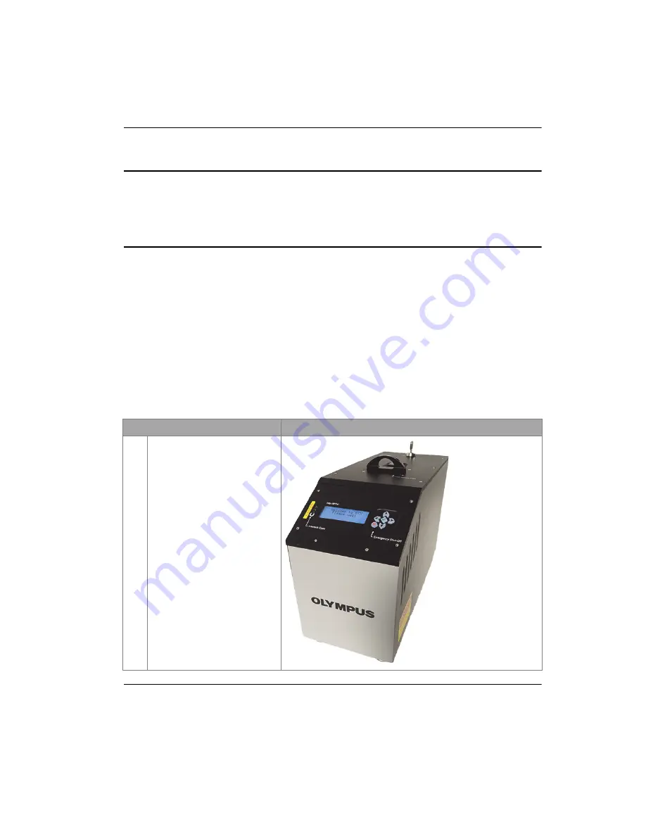
Table 2 BTX III components
Component
BTX III — all models
1
BTX III analyzer
Summary of Contents for BIX III
Page 6: ...Table of Contents vi 10 015490 01EN Rev 2 June 2020...
Page 8: ...10 015490 01EN Rev 2 June 2020 List of Abbreviations viii...
Page 12: ...10 015490 01EN Rev 2 June 2020 Labels and Symbols 4...
Page 28: ...10 015490 01EN Rev 2 June 2020 Introduction 20...
Page 36: ...10 015490 01EN Rev 2 June 2020 Chapter 1 28...
Page 64: ...10 015490 01EN Rev 2 June 2020 Chapter 4 56...
Page 82: ...10 015490 01EN Rev 2 June 2020 Chapter 5 74...
Page 84: ...10 015490 01EN Rev 2 June 2020 Appendix A 76...
Page 100: ...10 015490 01EN Rev 2 June 2020 List of Tables 92...


