


6-17
6.6 Attaching the 2-Bin tray
Packaging contents:
(1) 2-Bin unit (with connection cable) .......................................................................1
(2) Screws ................................................................................................................4
(3) Paper tray for the 2-Bin unit ................................................................................1
Note: When it is absolutely necessary to touch the ICs and other electrical components on the board,
be sure to ground your body.
Note: Make sure to turn off the fax machine and unplug the power cable before proceeding the
following steps.
Installation
1. Remove the REAR COVER.
2. Remove the TOP LEFT COVER.
3. Remove the OPTION COVER A.
4. Remove the EXIT TRAY.
5. Remove the RX EXIT COVER.
6. Separate the RX EXIT COVER A and B.
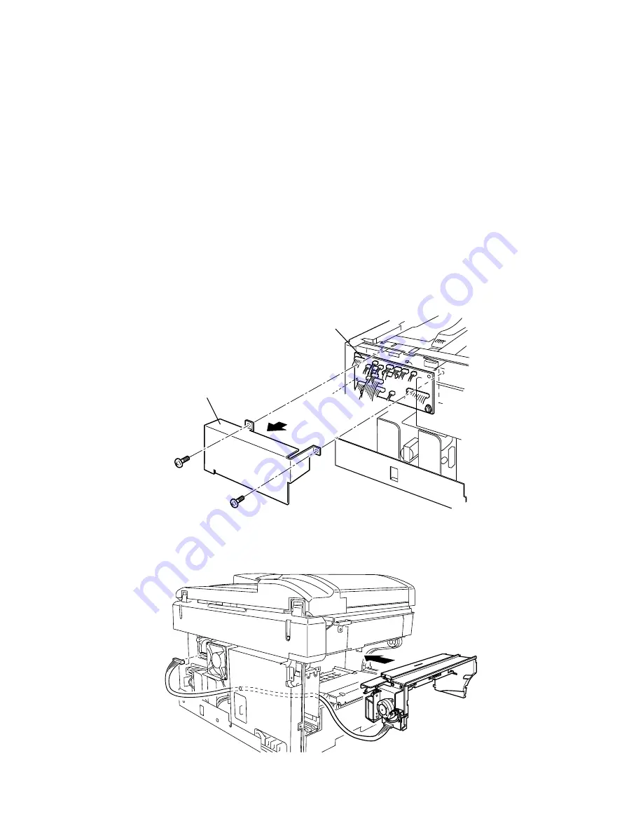
7. Remove the PCB SHIELD. Do not need to remove the CONNECT PRINTER PCB.
PCB shield
Printer connect PCB
8. Attach the 2-Bin tray to the machine, while passing the connection harness through the machine
frame.
9. Connect the connection harness to the connector P1314 on the CONNECT PRINTER PCB.
Note: The connection cable is not such long actually.
Summary of Contents for OKIOFFICE 1200
Page 1: ...OKIOFFICE 1200 1600 FIELD ENGINEERING MANUAL Version 2 0 11 June 2002...
Page 7: ...iv Packaging contents 6 22 Installation 6 22 Setting of the Paper Size 6 25...
Page 12: ...2 2 OKIOFFICE 1200 Interconnect Block Diagram 2 2 OKIOFFICE 1200 Connection Diagram 2 2...
Page 13: ...2 3 OKIOFFICE 1600 Interconnect Block Diagram 1 2 OKIOFFICE 1600 Connection Diagram 1 2...
Page 14: ...2 4 OKIOFFICE 1600 Interconnect Block Diagram 2 2 OKIOFFICE 1600 Connection Diagram 2 2...