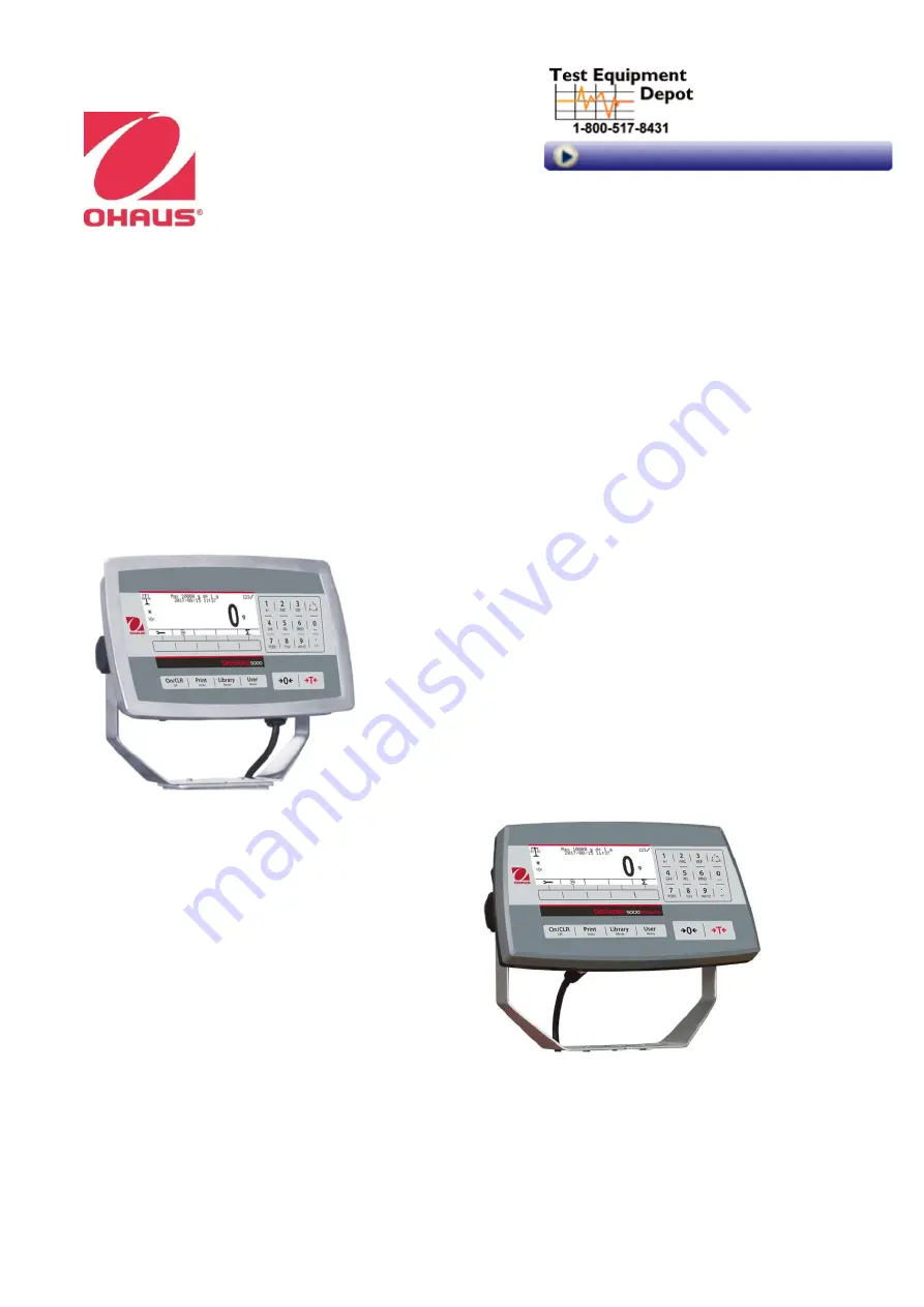
Defender
5000 Indicators
Service Manual
TD52P
TD52XW
99 Washington Street Melrose, MA 02176
Phone
781-665-
1400
Toll Free 1-800-517-8431
Visit us at www.T
estEquipmentDepot.com
Page 1: ...Defender 5000 Indicators Service Manual TD52P TD52XW 99 Washington Street Melrose MA 02176 Phone 781 665 1400 Toll Free 1 800 517 8431 Visit us at www TestEquipmentDepot com...
Page 2: ...5 CONTROL FUNCTIONS 6 1 6 EXTERNAL CONNECTIONS 7 1 6 1 Scale Base with Connector 7 1 6 2 RS232 interface Cable to TD52P 7 1 6 3 AC Power to TD52P 7 1 6 4 AC Power to TD52XW 7 1 6 5 Battery Power 7 1...
Page 3: ...lity 20 2 5 2 Zero Range 20 2 5 3 Filter Level 20 2 5 4 Auto Zero Tracking 21 2 5 5 Auto Dim 21 2 5 6 ScreenSaver 21 2 5 7 Auto Off 21 2 5 8 Adjust Contrast 21 2 5 9 Reset 21 2 6 Discrete I O 22 2 7 W...
Page 4: ...Reset 30 2 10 5 Board Info 30 3 MAINTENANCE 30 3 1 Model T52P Cleaning 30 3 2 Model TD52XW Cleaning 30 3 3 Troubleshooting 31 3 4 Service Information 31 4 TECHNICAL DATA 32 4 1 Specifications 32 4 2 A...
Page 5: ...ng hazard Use only approved accessories and peripherals Operate the equipment only under ambient conditions specified in these instructions Disconnect the equipment from the power supply when cleaning...
Page 6: ...s open windows people walking by fans etc Area must be clean and air must not contain excessive dust particles Work surface must be stable and level Work surface must not be exposed to direct sunlight...
Page 7: ...he 1 Volt dc position 3 Soldering Iron solder and flux remover 1 4 OVERVIEW OF PARTS AND CONTROLS 1 4 1 TD52P TABLE 1 1 TD52P PARTS Item Description 1 Data Label 2 Front Housing 3 Control Panel 4 Moun...
Page 8: ...TD52XW PARTS Item Description 1 Control Panel 2 Front Housing 3 Screw 6 4 Adjusting knob 2 5 Rear Housing 6 Mounting Bracket 7 Load Cell Connector 8 Strain Relief for Option 9 Power Cord 10 Strain Re...
Page 9: ...OARD Figure 1 3 Main PC Board TABLE 1 3 MAIN PC BOARD Item Description 1 IO Analog RS232 RS485 USB Device J11 2 SD Card J8 3 Rechargeable Battery Pack J9 4 USB Host Ethernet J4 5 Security Switch SW1 6...
Page 10: ...uppercase input To enter Z press 5 times in the mode of lowercase input To enter 0 press the button in the mode of numeric input To enter a space press the button in the mode of uppercase or lower cas...
Page 11: ...5 Battery Power The indicator can be operated on a rechargeable battery pack not supplied when AC power is not available It will automatically switch to battery operation if there is power failure or...
Page 12: ...hite load cell connector from the main PCBA board red circle 3 Remove the metal terminal Figure 1 1 item 12 connector from the rear housing green circle Installing Cables and Connectors In order to me...
Page 13: ...ion jumper is not required Figure 1 7 shows the terminal definitions for the analog load cell terminal strip Note that when using four wire load cells jumpers must be placed between the Excitation and...
Page 14: ...SD Socket left SD Card Installed right 1 8 TD52XW Rear Housing Orientation The TD52XW is delivered in the wall mount orientation with the connections exiting below the display The rear housing may be...
Page 15: ...ent 2 Capacity Auto Dim Dynamic 2 Graduation Brightness Reset Language Screensaver Power On Zero Auto Off Power On Unit Base Auto Off Key Beep Adjust Contrast Transaction Counter Reset Next Transactio...
Page 16: ...eset Print Setup Assignment Select Template Edit Template Edit String Reset Ethernet Configuration Host Name MAC Address Port Version DHCP IP Address Subnet Mask Gateway Primary DNS Secondary DNS Alt...
Page 17: ...Value 0 any valid value below the high limit Full Scale Value Desired source value scale capacity Cal Output Zero Cal Output Full SD Card Maintenance Library Export Menu Memory Mode Import Menu Link t...
Page 18: ...nu The TD52 indicator offers three calibration methods Zero Calibration Span Calibration and Linearity Calibration NOTES 1 Make sure that appropriate calibration masses are available before calibratio...
Page 19: ...should be performed after Zero Calibration Calibration procedures Long press the button to enter the Main Menu Press the soft key corresponding to the icon to enter the Calibration sub menu Scroll to...
Page 20: ...press the button to enter the Main Menu Press the soft key corresponding to the icon to enter the Calibration sub menu Scroll to Linearity Calibration using the soft key corresponding to the icon Pre...
Page 21: ...c keypad After editing press the soft key corresponding to the icon to exit the menu Note See table 4 3 for GEO values 2 4 Setup Menu When the Indicator connects to a scale base for the first time ent...
Page 22: ...l When Single range is selected the additional parameters available are 1 Capacity 1 Graduation When Dual range is selected the terminal functions with two ranges each with its own capacity and gradua...
Page 23: ...not all settings are available for each capacity 2 4 5 Language Set the language displayed for menus and displayed messages English Deutsch Fran ais Italiano Polski Spanish 2 4 6 Power On Zero Zero t...
Page 24: ...functionality Default settings are bold Read Out Options Stability 0 5d 1d 2d 5d Zero Range 2 100 Filter Level Low Medium High Auto Zero Track Off 0 5d 1d 3d Backlight Off 1min 2min 5min 10min Always...
Page 25: ...klight turns off after 5 minute of no activity 10 min backlight turns off after 10 minute of no activity Always on Off 2 5 6 ScreenSaver Set whether the screensaver is enabled after the selected time...
Page 26: ...d Underload Zero Discrete Output3 Off Overload Underload Zero Discrete Output4 Off Overload Underload Zero Counting Enable On Off Discrete Input1 Off Zero Tare Clear Tare Print Unit Accumulate Discret...
Page 27: ...e bold NOTE Due to national laws the indicator may not include some of the units of measure listed If the Security Switch is set to ON the Units are locked at their current setting 2 7 1 Gram g Set th...
Page 28: ...Factor by 10 1x10 1 2 multiply the Factor by 100 1x10 2 Least Significant Digit LSD Set the graduation Settings of 0 5 1 2 5 10 100 are available The Custom Unit s name can be customized up to 3 chara...
Page 29: ...xternal communication methods and to set printing parameters Data may be output to either a printer or PC Factory default settings are shown in bold 2 9 1 RS232 2 nd RS232 Configuration Communication...
Page 30: ...its Set the stop bits 1 BIT 2 BIT 2 9 1 4 Handshake Set the flow control method NONE no handshaking XON XOFF XON XOFF handshaking HARDWARE hardware handshaking COM1 menu only 2 9 1 5 Alternate Print C...
Page 31: ...rval If Interval is selected the sub menu Time will display INTERVAL printing occurs at the defined time interval The time interval can be set through the numeric keypad Settings of 1 to 3600 seconds...
Page 32: ...a template first select the field number from 1 to 50 in the first selection box then select the item for that field in the second selection box Using this method a template of up to 50 fields can be...
Page 33: ...9 6 Bluetooth Configuration Please refer to Bluetooth Configuration in the Defender 5000 USB Host Instruction Manual 2 9 7 Analog Please refer to Analog Configuration in the Defender 5000 Analog Kit I...
Page 34: ...ter this Menu you will find the software version and the PCB series number 3 MAINTENANCE CAUTION DISCONNECT THE UNIT FROM THE POWER SUPPLY BEFORE CLEANING 3 1Model T52P Cleaning The housing may be cle...
Page 35: ...rd may need to be set to the Off position Error 8 1 Weight reading exceeds Power On Zero limit Remove load from scale Recalibrate scale Error 8 2 Weight reading below Power On Zero limit Add load to s...
Page 36: ...Pound Ounce Pound Ounce Tonne Metric Tonne Ton Short Ton Custom Weighing modes Basic weighing Percent weighing Piece Counting with Optimized APW Animal weighing Dynamic weighing Check weighing Display...
Page 37: ...Interface USB Host 30424021 Light Tower Kit 3 Colors OHAUS 30424022 In use cover Kit TD52P 30424023 In use cover Kit TD52XW 30424026 Wall Mount Kit SST 30424027 Wall Mount Kit CS 30424409 Extension ca...
Page 38: ...5 14 14 13 13 12 12 11 42 19 43 26 17 16 16 15 15 14 14 13 13 12 12 43 26 44 32 17 17 16 16 15 15 14 14 13 13 12 44 32 45 38 18 17 17 16 16 15 15 14 14 13 13 45 38 46 45 18 18 17 17 16 16 15 15 14 14...
Page 39: ...rcuit Board PCB Replacement Repairs are not recommended on the PCB Replacement is recommended rather than repairing Replace the PCB for any of the following reasons Display is defective characters mis...
Page 40: ...36 Defender 5000 Indicators Service Manual 4 Remove the Seal and 3 screws for the LFT TD52P Wire Seal TD52P Paper Seal 5 Carefully separate the Top Housing and Bottom Housing...
Page 41: ...c discharge may damage some components 8 Carefully re position the replacement PCB over the screw holes in the Top Cover Re insert and tighten the screws 9 Reconnect the Cable Sets removed in Step 6 1...
Page 42: ...Indicators Service Manual 3 Carefully separate the Top Housing and Bottom Housing 4 If the indicator comes with the optional RS232 kit kindly remove from the PCB cover via removing 2 screws and the c...
Page 43: ...ove the red pad in the direction as picture shown 6 Remove the screw in the red circle and the power connectors from main PCBA and loadcell cable then separate the cover of main PCBA pry the side of c...
Page 44: ...sert and tighten the screws 9 Reconnect the Cable Sets removed in Step 5 10 Reconnect the optional RS232 PCBA 11 After replacing with a new Main PCBA kindly refer to Appendix A and configure the main...
Page 45: ...th the new one 5 2 3 TD52XW 1 Follow the Steps 1 7 of the PCB Replacement 5 1 2 2 Remove 5 screws on the PCBA Support 3 Take out the LCD and replace with the new one 5 3 Cable Set Replacement Cables s...
Page 46: ...h the cable set is to be replaced In the case of the TD52 s battery remove the quick connect tabs that hold the cables in place 3 Reconnect the wires to the PCB 5 3 Function Label Replacement 1 Isolat...
Page 47: ...he AC power source 2 Separate the Top Housing and Bottom Housing follow the step in Section 5 1 3 Remove the cable connector from the Transformer to the Main PCBA 4 Remove the cable connector from the...
Page 48: ...vice Manual 8 Secure the Transformer with four screws and reserve step 2 for Housing assembly 9 Connect the Indicator to AC power and test it Note Kindly take note of the cable routing from the Transf...
Page 49: ...cording to their region 1 Down load and install OHAUS Service and Repair Tools Version 2 2 0 0 and later 2 Open the software and select Repair Tool and click Next 3 Select TD52 under Product Selection...
Page 50: ...Indicators Service Manual 8 Turn OFF and ON the indicator and check if the configuration is correct 9 If the process fail kindly check the below The communication cable pin configuration The Indicator...
Page 51: ...the RS232 cable which in included in the cable set kit 30427860 please connect the RS232 cable to the socket as the picture below 1 Down load and install OHAUS Service and Repair Tools Version 2 2 0 0...
Page 52: ...ower and press the ON button follow by the instruction in the picture below 8 You will see the below window screen when it s in the process of the software download 9 You will see the below window scr...
Page 53: ...ile in the folder Update with the name 30427649 mot 3 Insert the Micro SD card into the SD card Slot Make sure indicator is powered off for this step TD52P TD52XW 4 Power on and long press the button...
Page 54: ...nder 5000 Indicators Service Manual 7 The indicator will be switched off automatically when it s done with the software upgrading 8 Switch on the indicator to check the software version when program s...
Page 55: ...30479277A P N 30479277A 2018 OHAUS Corporation all rights reserved 99 Washington Street Melrose MA 02176 Phone 781 665 1400 Toll Free 1 800 517 8431 Visit us at www TestEquipmentDepot com...