Symbols in figures
Introduction
If not indicated otherwise, diagrams and illustrations of actions depict the starting position
of the respective component for the described step.
To ease understanding, the illustrations depict the components that are directly relevant
to the immediate context in a larger line thickness.
Note:
As a result of the continuous technical further development, it may be that some of the
details on the images in the documentation are not always completely up-to-date with
the delivered printing system.
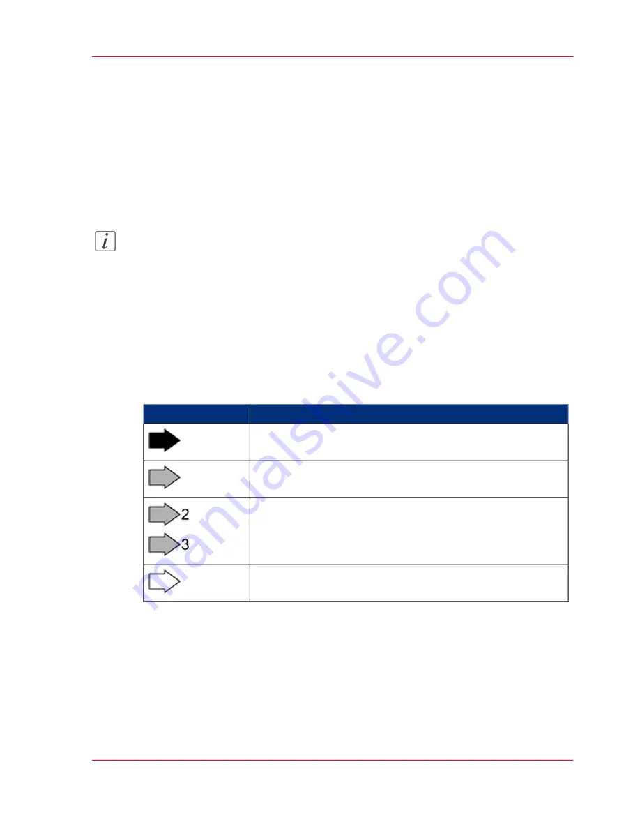
Arrows
Arrows denote the positions where you should perform an action or observe something
in particular. The colors of the arrows denote the type of actions and the sequence in
which they are performed:
#
Meaning
Arrow
Black arrow: Direction arrow
Perform this action first
Grey arrow: Direction arrow
Perform this action next
If further actions are depicted in an illustration, the numbers
on the arrows indicate the sequence of these further actions.
White arrow: Note arrow
An action should be performed in this area.
Overview Graphics
To provide a clear overview, the VarioStream 9000 and ColorStream printing systems
also indicate the side of the printing system where the action is to be performed.
Chapter 1 - Notes on the Printing System Documentation
25
Symbols in figures
Summary of Contents for ColorStream
Page 1: ...o More Power When Printing Oc ColorStream User Manual Continuous Printing System...
Page 10: ...10 Contents...
Page 11: ...Chapter 1 Notes on the Printing System Documentation...
Page 30: ...Chapter 1 Notes on the Printing System Documentation 30 Statutory requirements...
Page 31: ...Chapter 2 Safety...
Page 50: ...Chapter 2 Safety 50 Accident prevention regulation for replacement carts option...
Page 51: ...Chapter 3 Description of the Printing System...
Page 80: ...Chapter 3 Description of the Printing System 80 Paper specifications...
Page 81: ...Chapter 4 Description of the Opera tor Panel...
Page 105: ...Chapter 5 Working with the Operator Panel...
Page 137: ...Chapter 6 Operating the Printing System...
Page 203: ...Chapter 6 Operating the Printing System 203 5C_PrintQualityInspection 600 Test Print Job...
Page 204: ...Chapter 6 Operating the Printing System 204 5C_PrintQualityInspection 600 Test Print Job...
Page 267: ...Chapter 7 Cleaning the Printing Sys tem...
Page 310: ...Chapter 7 Cleaning the Printing System 310 Cleaning the Developer Station Shelf Optional...
Page 311: ...Chapter 8 Replacing Consumables...
Page 344: ...Chapter 8 Replacing Consumables 344 Fill in Developer...
Page 345: ...Chapter 9 Replacing Expendables...
Page 472: ...Chapter 9 Replacing Expendables 472 Replacing Expendables in Expert Mode...
Page 473: ...Chapter 10 Correcting Errors...
Page 490: ...Chapter 10 Correcting Errors 490 Correcting Print Image Errors...
Page 491: ...Appendix A Technical Data...
Page 506: ...Appendix A Technical Data 506 Ruler for Checking Paper Path Synchronization...
Page 507: ...Appendix B Comments...
Page 521: ...3...
Page 522: ...3...
Page 523: ...3...


