-
24
-
PROCESSOR BOOSTER & CYLINDER
OPERATING PRINCIPLE
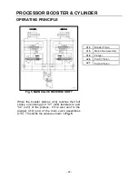
Fig. 7 VALVE SHIFT TO FORWARD STROKE
When the booster pistons (c14) reach full reverse
stroke, oil drains out of the plunger (c19) ends of the
main control valves (c15) through ports C2 (c27)
and C3 (c28) of the booster pistons. The main
control valve springs move the main control valve
spools toward the plungers. This places the main
control valves in position to direct oil to the booster
pistons to start the next forward piston stroke.
These forward and reverse piston strokes will
continue as long as the excavator’s control valve
(k7) is shifted to send hydraulic flow to the boosters
and cylinders and that there is sufficient resistance
(load)
to keep the booster active.
c14
Booster Piston
c15
Main Valve Assembly
c19
Plunger
c27
Port C2 Piston
c28
Port C3 Piston
k7
Carrier Control Valve
Summary of Contents for M35G
Page 13: ... 13 SERIAL NUMBER LOCATION M35 ...
Page 115: ... 115 WARRANTY STATEMENTS ...
Page 116: ... 116 WARRANTY STATEMENTS ...


