-
23
-
PROCESSOR BOOSTER & CYLINDER
OPERATING PRINCIPLE
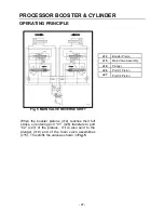
Fig. 6 REVERSE PISTON STROKE
When the main valve assemblies (c15) have been
shifted, oil is directed through the main valve
assemblies to oil chambers (v3) and (v4) of the
booster pistons (c14). This strokes the booster
pistons toward oil chambers (v2). The oil in
chambers (v2) is intensified and sent through check
valves 3 (c23) to the base end of the cylinders
(c11). Pilot check valves (c20) and check valves 4
(c24) are also closed at this time.
c11
Jaw Cylinder
c14
Booster Piston
c15
Main Valve Assembly
c20
Pilot Check Valve
Assembly
c23
Check Valve 3 - booster
sleeve "B"
c24
Check Valve 4 - booster
sleeve "A"
v2
Oil Chamber - 2
v3
Oil Chamber - 3
v4
Oil Chamber - 4
Summary of Contents for M35G
Page 13: ... 13 SERIAL NUMBER LOCATION M35 ...
Page 115: ... 115 WARRANTY STATEMENTS ...
Page 116: ... 116 WARRANTY STATEMENTS ...


