-
21
-
PROCESSOR BOOSTER & CYLINDER
OPERATING PRINCIPLE
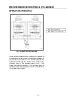
Fig. 4 FORWARD PISTON STROKE
The hydraulic oil that has passed through the
booster valves (c15), flows into rear oil chambers v1
and v2 of the booster pistons (c14) and strokes it
toward oil chambers v4. Because the area of the
booster pistons in oil chambers v1 is greater than
the area in chambers v4, the pressure in oil
chambers v4 is intensified. The higher pressure oil
is pushed through check valves (c24) to the base
end of the cylinders (c11) and closes check valves
(c23).
c11
Jaw Cylinder
c14
Booster Piston
c15
Main Valve Assembly
c23
Check Valve 3 - booster
sleeve "B"
c24
Check Valve 4 - booster
sleeve "A"
v1
Oil Chamber - 1
v2
Oil Chamber - 2
v4
Oil Chamber - 4
Summary of Contents for M35G
Page 13: ... 13 SERIAL NUMBER LOCATION M35 ...
Page 115: ... 115 WARRANTY STATEMENTS ...
Page 116: ... 116 WARRANTY STATEMENTS ...


