background image

86

Chapter 4 Using VLAN Manager

208963-B


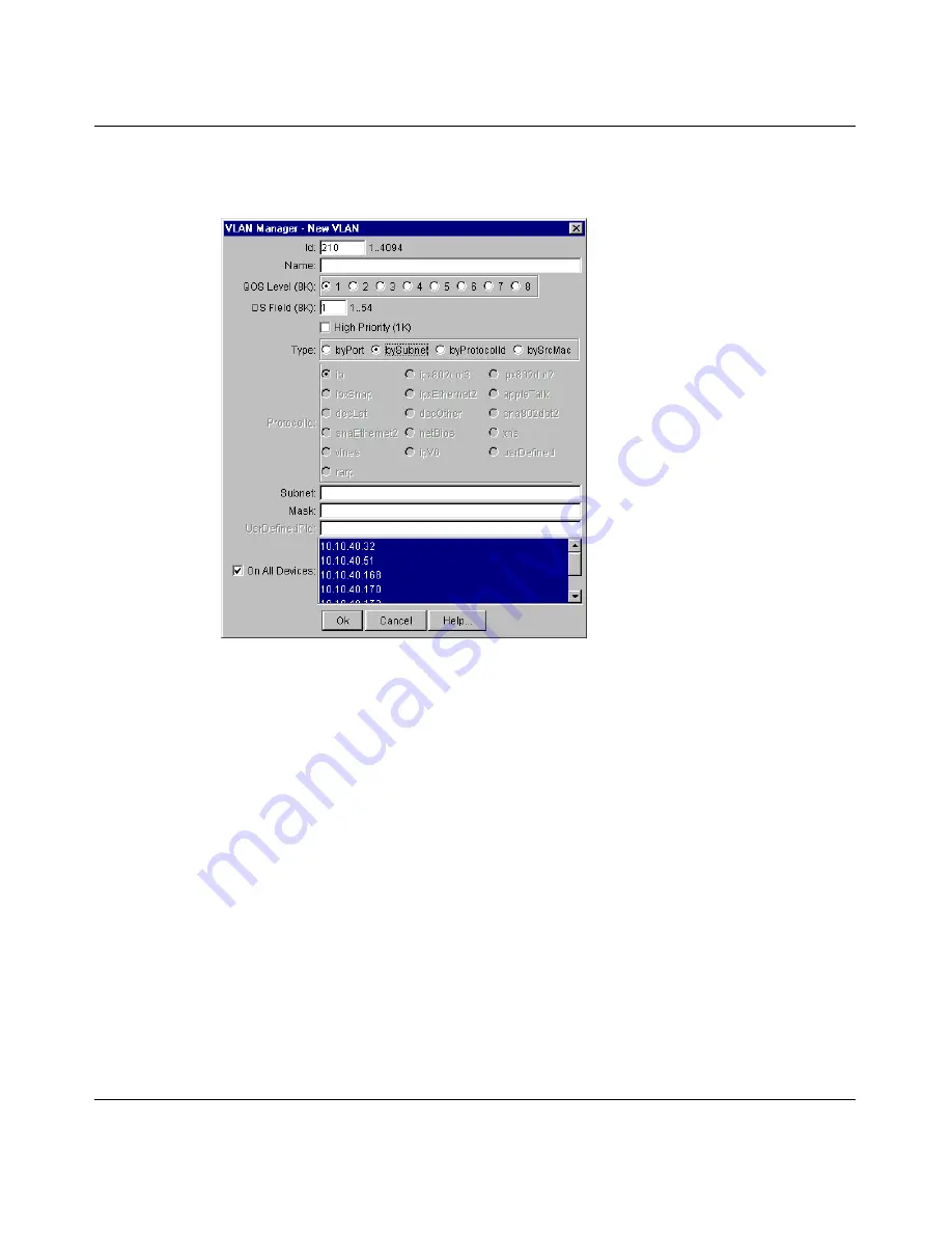
The New VLAN dialog box opens 

(Figure 33)

.

Figure 33   

New VLAN dialog box with bySubnet selected

3

Type the VLAN ID.

The value can be from 1 to 4094, as long as it is not already in use. (The 
default VLAN has a VLAN ID of 1.)

4

Type the VLAN name (optional).

If no name is entered, a default is created.

5

For a Passport 8600 switch, you the QoS Level (optional)

6

For a Passport 8600 switch, type the Differentiated Services (DS) Field 
(optional).

7

For a Passport 1000 Series switch, specify if the VLAN traffic will be tagged 
as High Priority (optional).

8

In the Type option, select bySubnet.

Other items in the dialog box that apply to a subnet-based VLAN are 
activated.

9

In the Subnet text box, type the source IP subnet address.

Summary of Contents for Optivity Switch

Page 1: ...Part No 208963 B March 2001 4401 Great America Parkway Santa Clara CA 95054 Using Optivity Switch Manager Release 1 1 0 0...

Page 2: ...ng its use reproduction and disclosure are as set forth in the Commercial Computer Software Restricted Rights clause at FAR 52 227 19 Statement of conditions In the interest of improving internal desi...

Page 3: ...wise disclose to any third party the Software or any information about the operation design performance or implementation of the Software and user manuals that is confidential to Nortel Networks and i...

Page 4: ...ation of the Nortel Networks copyright those restrictions relating to use and disclosure of Nortel Networks confidential information shall continue in effect Licensee may terminate this license at any...

Page 5: ...managers 24 VLAN Manager 25 MultiLink Trunking Manager 25 Multicast Manager 26 Log Manager 26 Device Manager 26 Chapter 2 Using Optivity Switch Manager 27 Starting Optivity Switch Manager 28 Using the...

Page 6: ...g Optivity Switch Manager 47 Discovering your network 47 Discovering devices on a network 48 Restricting discovery 51 Layout slider 52 Accessing devices within different SNMP communities 53 Chapter 4...

Page 7: ...reating a VLAN 82 Creating a port based VLAN 83 Creating a source IP subnet based VLAN 85 Creating a protocol based VLAN 87 User defined protocols in a protocol based VLAN 89 Creating a source MAC add...

Page 8: ...g a new MLT on a pair of devices 113 Viewing MLT port information 115 Editing a port on an MLT 116 Deleting an MLT 117 Editing an MLT 117 Highlighting devices and MLT links in Optivity Switch Manager...

Page 9: ...formation 154 Route tab 154 Viewing Multicast Groups information 156 Source Subnets tab 157 Receivers tab 159 Viewing Multicast Manager information in Optivity Switch Manager 160 Highlighting a multic...

Page 10: ...ng a syslog file 171 Exporting a log file 174 Locating specific log entries 174 Filtering log entries 176 Appendix A Additional reference sources 179 Appendix B Troubleshooting and error messages 181...

Page 11: ...og box 48 Figure 12 Restrict Discovery dialog box 52 Figure 13 Communities dialog box 54 Figure 14 VLAN Manager window 58 Figure 15 VLAN Manager navigation pane 61 Figure 16 Default 1 folder view in t...

Page 12: ...dialog box 105 Figure 43 Trunk table 107 Figure 44 No Trunk table 108 Figure 45 Isolated Device table 110 Figure 46 Insert MLT dialog box one device selected 112 Figure 47 Trunk table for a pair of de...

Page 13: ...cast Group table 157 Figure 76 Source Subnets tab 158 Figure 77 Receivers tab Multicast Groups 159 Figure 78 Optivity Switch Manager with forwarding node highlighted 162 Figure 79 Optivity Switch Mana...

Page 14: ...14 Figures 208963 B...

Page 15: ...58 Table 12 VLAN Manager menus and commands 59 Table 13 VLAN Manager status bar fields 62 Table 14 Port membership types and STGs 64 Table 15 Unassigned Ports table fields 65 Table 16 Tagging Ports ta...

Page 16: ...ble 40 Receiver tab fields 134 Table 41 Sender tab fields 136 Table 42 Static tab fields 137 Table 43 Access tab fields 139 Table 44 Cache tab fields 141 Table 45 Interface tab fields 143 Table 46 Gro...

Page 17: ...k This guide provides information about installing the Optivity Switch Manager software and using the features and capabilities of Optivity Switch Manager s graphical user interface GUI Before you beg...

Page 18: ...new terms book titles and variables in command syntax descriptions Where a variable is two or more words the words are connected by an underscore Example If the command syntax is show at valid_route...

Page 19: ...c Switch Management Release 3 1 part number 211255 A Describes the command line interface CLI structure and the commands used to perform basic switch management operations such as modifying the switch...

Page 20: ...Series switch including procedures and illustrations of pertinent screens Reference for the BayStack 350 410 450 Management Software Operations Version 3 1 part number 210245 B Describes how to use D...

Page 21: ...following Nortel Networks Technical Solutions Centers An Express Routing Code ERC is available for many Nortel Networks products and services When you use an ERC your call is routed to a technical su...

Page 22: ...22 Preface 208963 B...

Page 23: ...nce your network is discovered you can monitor manage and configure protocols and settings in devices in the network using the following submanagers within Optivity Switch Manager VLAN Manager MultiLi...

Page 24: ...y map through Optivity Switch Manager Access control and security using community strings Network discovery that you can specify to be as large or small as you want Ability to save the layout of a dis...

Page 25: ...devices View VLAN information membership and port configuration information in tabular format View Spanning Tree Protocol information such as members of spanning tree groups STGs and Spanning Tree Pr...

Page 26: ...formation For more information about Log Manager refer to Chapter 7 Using Log Manager on page 165 Device Manager Device Manager is a standalone application that you can launch either from Optivity Swi...

Page 27: ...Optivity Switch Manager For information about how to install Optivity Switch Manager refer to Installing Optivity Switch Manager Release 1 1 0 0 This chapter includes the following topics Starting Op...

Page 28: ...vironment double click the Optivity Switch Manager shortcut icon on your desktop if it is present In a Solaris terminal window enter OSM in the location where Optivity Switch Manager has been installe...

Page 29: ...he initial discovery other Optivity Switch Manager submanager applications allow you to monitor or configure discovered devices Figure 1 shows the Optivity Switch Manager window Figure 1 Optivity Swit...

Page 30: ...menu bar The menu bar provides menus and commands for operating Optivity Switch Manager and for accessing Device Manager VLAN Manager MultiLink Trunking Manager Multicast Manager and Log Manager Tabl...

Page 31: ...rameters to find a device in the topology map Select All Selects all devices within a supported product family Passport 1000 Series switches Passport 8000 Series switches or BayStack switches View Lin...

Page 32: ...nsaved Configurations Opens the Find Unsaved Configurations dialog box that lists the devices with unsaved changes in their configuration files The dialog box contains the device IP address the time d...

Page 33: ...e items in the Find Unsaved Configurations dialog box Help Contents F1 Opens a Web browser application and loads Help files Online Support Opens a Web browser that loads the Nortel Networks Customer S...

Page 34: ...ion To access the shortcut menu The shortcut menu opens Figure 3 Figure 3 Shortcut menu Table 3 Find Unsaved Configurations dialog box items Item Description Device The IP address system name or host...

Page 35: ...ibes the items in the Device Properties dialog box Table 4 Device Properties dialog box items Item Description Name The IP address system name or host name of the device Type The chassis type SysName...

Page 36: ...Optivity Switch Manager Log Manager Print Prints the topology map Note The application does not paginate the map that is break the map printing into several pages To print a portion of the map ensure...

Page 37: ...submanager Optivity Switch Manager Multicast Manager Starts the Multicast Manager submanager Optivity Switch Manager Help Opens online Help Optivity Switch Manager VLAN Manager MultiLink Trunking Man...

Page 38: ...Multicast Manager Table 6 Status bar fields Field Description Message Located on the left the message field displays information about Menu commands and toolbar buttons Optivity Switch Manager and su...

Page 39: ...tch Manager contents pane Figure 5 Figure 5 Optivity Switch Manager topology map The Optivity Switch Manager topology map uses icons to represent the types of network devices discovered Some of the de...

Page 40: ...nd its submanagers Passport 8K Passport 8000 Series switch This device can be configured and monitored by Optivity Switch Manager and its submanagers BayStack or Business Policy Switch 2000 BayStack 3...

Page 41: ...o adjust the scale of the topology map Figure 6 Scale slider You can display the map up to sixteen times larger Working with the network topology map After a network topology map is loaded into the Op...

Page 42: ...scovery process described in Discovering devices on a network on page 48 To reload a saved topology map 1 Do one of the following From the Optivity Switch Manager menu bar choose File Open On the keyb...

Page 43: ...y map it is stored with a topo file extension If you do not save a topology with a specific file name Optivity Switch Manager attempts to save the current map to the default topo file To save a topolo...

Page 44: ...Optivity Switch Manager menu bar choose Edit Find Device in Map On the keyboard press Ctrl F On the Optivity Switch Manager toolbar click Find The Find Device dialog box opens Figure 9 Figure 9 Find D...

Page 45: ...s icons are crowded together and the port numbers and IP addresses overlap each other To improve readability of the map you can automatically or manually adjust the layout Figure 10 Optivity Switch Ma...

Page 46: ...Navigator or Microsoft Internet Explorer opens to display Help files You can use the contents frame or the Help index to locate information To access Help From the Optivity Switch Manager menu bar ch...

Page 47: ...ork After getting the information about the neighbors of the seed device Optivity Switch Manager queries the neighbor devices for their topology tables Optivity Switch Manager then selects the appropr...

Page 48: ...cation queries the addresses The Preferences dialog box specifies the seed address and defines the scope of the discovery process To discover a network 1 From the Optivity Switch Manager menu bar choo...

Page 49: ...Description Discovery Seed Address es The IP address es of one or more devices that Optivity Switch Manager queries using SNMP to start the discovery process For a list of supported devices see Instal...

Page 50: ...Truncates Internet host name domains Example nortelnetworks com becomes nortelnetworks Non highlighted area Allows you to select an option for viewing inactive devices The options are Dimmed Non high...

Page 51: ...log box opens Figure 12 SNMP Retry Count The number of times between 0 and 5 Optivity Switch Manager tries to connect to a device using SNMP The default is 1 Timeout The amount of time between 3 and 1...

Page 52: ...readability of the topology map It adjusts the layout of the devices in the network topology using the Spring algorithm which balances the distances between devices and minimizes the number of crossi...

Page 53: ...ty Switch Manager typically have two passwords or communities for read and write operations on that device The two passwords are public open access and private restrictive access By default Optivity S...

Page 54: ...or the IP address of a single device Default is 0 0 0 0 to include all devices Note Optivity Switch Manager uses zero 0 as a wildcard to associate SNMP communities with groups of devices You can plac...

Page 55: ...Manager page 63 Managing spanning tree groups STGs page 79 Managing a VLAN page 82 Highlighting STGs and VLANs in the Optivity Switch Manager contents pane page 93 What is VLAN Manager VLAN Manager e...

Page 56: ...STG and a network may include multiple instances of STGs All the devices supported by Optivity Switch Manager support at least one STG The Passport 1000 Series switch and the Passport 8600 modules sup...

Page 57: ...ty Switch Manager contents pane such as which ports are blocking or forwarding You can also see which device is the root of the Spanning Tree configuration The following sections describe the VLAN Man...

Page 58: ...lays the submanager name Menu bar Provides access to all VLAN Manager commands Toolbar Provides quick access to commonly used VLAN Manager commands Navigation pane Provides a navigation tree showing V...

Page 59: ...a selected cell Paste Ctrl V Pastes the cell contents to a new location Insert Insert Opens the Insert dialog box where you insert an STG or VLAN on selected devices Delete Del Removes a selection and...

Page 60: ...ree expands to display the STG configuration information and then lists the VLANs associated with that STG In the navigation pane select the folder for which you want to view STG or VLAN information o...

Page 61: ...ity Switch Manager Release 1 1 0 0 Figure 15 VLAN Manager navigation pane Contents pane When you select a network resource in the navigation pane a table opens in the contents pane Figure 16 Figure 16...

Page 62: ...To find a network resource 1 Click any device in the navigation tree or contents pane and do one of the following From the VLAN Manager menu bar choose Edit Find In the navigation pane select an STG o...

Page 63: ...ane 4 Click Next VLAN Manager starts its search and highlights the first match that it finds or displays a message that it found no matches 5 If a first match was found click Next to find each subsequ...

Page 64: ...open in the contents pane Tagging Port that has tagging enabled and can belong to multiple STGs If a tagged frame is received on a tagged port with a VLAN ID specified in the tag the switch directs i...

Page 65: ...Figure 18 Unassigned Ports table Table 15 describes the Unassigned Ports table fields Viewing tagged Ports To view the devices and ports associated with tagged ports The Tagging Ports table opens in...

Page 66: ...To view IRPs on Passport 1000 Series switches The Isolated Routing Ports table opens in the contents pane Figure 20 Table 16 Tagging Ports table fields Field Description Device IP address system name...

Page 67: ...dge routing Ports To view bridge routing brouter ports on Passport 1000 Series switches and Passport 8000 Series switches The Bridge Routing Ports table opens in the contents pane Figure 21 Table 17 I...

Page 68: ...e instance of a Spanning Tree Group Refer to Table 10 on page 56 for the maximum STGs supported by each switch To view an STG The folder expands to show four icons representing types of information av...

Page 69: ...on pane Members To view the ports that are members of the STG The Members table opens in the contents pane Figure 23 Table 19 STG information icons Icon Name Representation Members Devices and ports t...

Page 70: ...ts to an STG 1 In the Members table select a device in the list 2 Double click in the PortMembers cell for the device to which you want to add port membership The PortMembers dialog box opens Figure 2...

Page 71: ...s dialog box 3 Select the port number s or click All for all the ports 4 Click Ok Viewing and configuring STG parameters You can view and configure STG parameters To view the configuration information...

Page 72: ...that the range for this parameter is related to the value of dot1dStp Time The default is 2000 20 seconds BridgeHelloTime The value in hundredths of a second that all bridges use for Hello Time when...

Page 73: ...e Status table Figure 26 opens in the contents pane Figure 26 Status table Table 22 describes the fields in the Status table TaggedBpduAddress A MAC address specifically for tagged BPDUs TaggedBpduVla...

Page 74: ...n any port before it is discarded in units of hundredths of a second This is the actual value that the bridge is currently using The default value is 2000 20 seconds HelloTime Amount of time in hundre...

Page 75: ...annot delete the default VLAN although you can remove ports from it Table 23 Root table fields Field Description Device IP address of a device in the STG BridgeAddress MAC address used by this bridge...

Page 76: ...d Description Device IP address system name or host name of the device PortMembers Ports that are assigned to the VLAN HighPriority In a Passport 1000 Series switch you can select HighPriority mode fo...

Page 77: ...AN This value can be in one of the following ranges Passport 1000 Series switch 257 to 512 Passport 8000 Series switch 2049 to 4096 Note This field does not apply to BayStack or Business Policy Switch...

Page 78: ...78 Chapter 4 Using VLAN Manager 208963 B The VLAN table opens Figure 29 in the contents pane Figure 29 VLAN table Table 24 on page 76 describes the fields in the VLAN table...

Page 79: ...panning tree group Creating a spanning tree group On a Passport 1000 Series switch or a Passport 8600 switch you can create new STGs The BayStack switches and the Business Policy Switch 2000 support o...

Page 80: ...specifically for tagged BPDUs TaggedBpduVlanId The VLAN tag associated with the STG This ID is used to tag BPDUs through a non IEEE tagging bridge to another Passport or BayStack switch Priority STP b...

Page 81: ...VLAN Manager toolbar click Delete BridgeHelloTime Value in hundredths of a second that all bridges use for Hello Time when this bridge is acting as the root The granularity of this timer is specified...

Page 82: ...the table view Managing a VLAN This section contains information about common operations you can perform when managing VLANs with VLAN Manager Creating a VLAN When you create VLANs using VLAN Manager...

Page 83: ...is in a VLAN the spanning tree group configuration for that port is lost A frame s VLAN membership is determined by the following order of precedence VLAN ID Source MAC based VLAN IP subnet based VLA...

Page 84: ...ame optional If no name is entered a default is created 5 For a Passport 8600 switch select the QoS Level optional 6 For a Passport 8600 switch type the Differentiated Services DS Field optional 7 For...

Page 85: ...menu bar choose Edit Insert On the toolbar click Insert Table 26 New VLAN dialog box items Item Description Id A number between 1 and 4 094 that identifies the new VLAN configured on the network Name...

Page 86: ...name optional If no name is entered a default is created 5 For a Passport 8600 switch you the QoS Level optional 6 For a Passport 8600 switch type the Differentiated Services DS Field optional 7 For...

Page 87: ...ist Click On All Devices to select all devices in the list 12 Click Ok 13 Do one of the following From the VLAN Manager menu bar choose Apply Changes On the VLAN Manager toolbar click Apply Changes Cr...

Page 88: ...the VLAN name optional If no name is entered a default is created 5 For a Passport 8600 switch select the QoS Level optional 6 For a Passport 8600 switch type the Differentiated Services DS Field opt...

Page 89: ...the following From the VLAN Manager menu bar choose Apply Changes On the VLAN Manager toolbar click Apply Changes User defined protocols in a protocol based VLAN You can create a protocol based VLAN...

Page 90: ...0000 through 0x05dc overlap with the 802 3 frame length PIDs of predefined protocols for example IP IPX AppleTalk PID 0x8100 reserved by 802 1Q to identify tagged frames PID0x9000 used by the diagnost...

Page 91: ...of 1 4 Type the VLAN name optional If no name is entered a default is created 5 For a Passport 8600 switch select the QoS Level optional 6 For a Passport 8600 switch type the Differentiated Services...

Page 92: ...N dialog box opens Figure 36 Figure 36 Edit Mac VLAN dialog box 12 Select Add From File and enter the file name of the text file containing the MAC addresses to added to the new MAC based VLAN You can...

Page 93: ...RPs and brouter ports Which ports are assigned to a particular spanning tree group STG Which device is the root of an STG and which ports are in the forwarding and blocking states Which ports are memb...

Page 94: ...ng STG port members When you select an STG in the VLAN Manager navigation pane you can view the devices and ports associated with that STG in the Optivity Switch Manager network topology map This view...

Page 95: ...bers icon The STG Members table opens in the VLAN Manager contents pane 2 From the VLAN Manager menu bar choose View Highlight Topology 3 Return to the Optivity Switch Manager window The devices conta...

Page 96: ...96 Chapter 4 Using VLAN Manager 208963 B Figure 38 Viewing STG port members Some of the STG port members...

Page 97: ...n To view STG root configuration in Optivity Switch Manager 1 In the navigation pane select an STG Root The Root table opens in the contents pane 2 From the VLAN Manager menu bar choose View Highlight...

Page 98: ...he root of the STG is 10 10 40 153 and the port in forwarding state is Port 9 on Slot 1 of 10 10 40 32 Note Update the View Highlight topology periodically to refresh the topology display because port...

Page 99: ...ing Manager next Starting MultiLink Trunking Manager page 100 MultiLink Trunking Manager window page 101 Using MultiLink Trunking Manager page 106 Managing MultiLink Trunks MLTs page 111 Highlighting...

Page 100: ...logy map Starting MultiLink Trunking Manager To start MultiLink Trunking Manager From the Optivity Switch Manager menu bar choose Tools MultiLink Trunking Manager On the keyboard press F3 On the Optiv...

Page 101: ...ndow parts Part Description Title bar Displays the submanager name Menu bar Provides access to all MultiLink Trunking Manager commands Toolbar Provides quick access to commonly used MultiLink Trunking...

Page 102: ...rd Copy Ctrl C Copies the contents of the selected cell Paste Ctrl V Pastes the cell contents when you select a new location Insert Opens the Insert dialog box where you insert an MLT on a selected de...

Page 103: ...k Trunking Manager navigation tree Figure 40 is located on the left side of the window and contains branches with the IP address of devices discovered by Optivity Switch Manager From the navigation tr...

Page 104: ...has two fields Table 30 describes the fields in the MultiLink Trunking Manager status bar Table 30 MultiLink Trunking Manager status bar fields Field Description Message Located on the left the messag...

Page 105: ...d press Ctrl F On the MultiLink Trunking Manager toolbar click Find The Find dialog box opens Figure 42 Figure 42 Find dialog box 2 In the Find text box type the text or number you are searching for 3...

Page 106: ...switch that links to another device in the network and has MLT configurations No trunk a switch that links to another device in the network but does not have an active MLT configured Isolated a switc...

Page 107: ...ress system name or host name of the device Id Number of the MLT assigned by MultiLink Trunking Manager Name Name given to the MLT PortMembers Ports that are assigned to the MLT PortType Type of port...

Page 108: ...are single links between two devices To view No trunk configurations The No Trunk table Figure 44 opens in the contents pane Figure 44 No Trunk table Table 32 describes the fields in the No Trunk tabl...

Page 109: ...ice table opens in the contents pane Figure 45 PortMembers Ports that are assigned to the MLT PortType Type of port on the MLT access or trunk VlanIds VLAN s to which the ports belong Enable Whether t...

Page 110: ...on Device IP address system name or host name of the device Id Number of the MLT Name Name given to the MLT PortMembers Ports that are assigned to the MLT PortType Type of port on the MLT access or tr...

Page 111: ...ports or you can connect the ports first and then configure the MLT Creating an MLT with one device When you create an MLT with one device MultiLink Trunking Manager considers only the ports that are...

Page 112: ...ports to be added to the MLT Inactive ports appear dimmed in the Ports box Table 34 Insert MLT dialog box items for a single device Item Description Node IP address of the first network device configu...

Page 113: ...ger considers port availability type of port and current links between both devices You cannot configure an MLT on an isolated device To create a new MLT between two devices 1 Select a device from the...

Page 114: ...ports to be added to the MLT In the Insert MLT dialog box port numbers are highlighted in green to indicate that the ports are already connected between the two devices Dimmed port numbers mean that...

Page 115: ...ype the name for one node the name is automatically added to the other node Ports Ports enabled on the MLT Type One of the following types of MLT Access Trunk The default is Access VlanIds VLAN IDs fo...

Page 116: ...port is up or down and what other device ports the port is connected to Editing a port on an MLT To edit a port on an existing MLT 1 In the navigation pane select an MLT The MLT table opens in the co...

Page 117: ...ultiLink Trunking Manager toolbar click Delete The Delete dialog box opens asking you to confirm the deletion Figure 51 Figure 51 Delete dialog box 2 Click Yes Editing an MLT To edit an MLT 1 In the n...

Page 118: ...opens in the MultiLink Trunking Manager contents pane Figure 52 Figure 52 Trunk table 2 From the MultiLink Trunking Manager menu bar choose View Highlight Topology 3 Return to the Optivity Switch Mana...

Page 119: ...Chapter 5 Using MultiLink Trunking Manager 119 Using Optivity Switch Manager Release 1 1 0 0 Figure 53 Highlight topology view in Optivity Switch Manager Highlighted Highlighted MLT link device device...

Page 120: ...120 Chapter 5 Using MultiLink Trunking Manager 208963 B...

Page 121: ...23 Using Multicast Manager page 130 Viewing Multicast Manager information in Optivity Switch Manager page 160 What is Multicast Manager Multicast Manager allows you to view devices within a network th...

Page 122: ...multicast datagrams When DVMRP is coupled with IGMP membership a multicast stream is learned from both the routers and directly attached hosts IGMP IGMP allows a host to register group memberships wi...

Page 123: ...Multicast Manager navigation tree Provide information about multicast groups with active members including information on group address source subnet and last reporters Display the multicast forwardi...

Page 124: ...ticast Manager commands Navigation pane Provides a navigation tree showing Multicast Manager protocols and groups Contents pane Displays information selected in the navigation pane Scroll bar Provides...

Page 125: ...Print dialog box where you set parameters to print Close Closes Multicast Manager Edit Undo Changes Ctrl Z Reverses any changes you made to a record Copy Ctrl C Copies the contents of the selected cel...

Page 126: ...l identifying the intermediate forwarding nodes In the navigation pane you can select the folder for which you want to view multicast information or use the Print command to print the navigation tree...

Page 127: ...5 Multicast Manager navigation pane Contents pane When you select a network resource in the navigation pane a table opens in the contents pane Figure 56 Note In this release tables are not available f...

Page 128: ...n the contents pane The example in Figure 56 shows the DVMRP information found on device 10 10 40 31 Status bar The Multicast Manager status bar is located at the bottom of the Multicast Manager windo...

Page 129: ...r search 3 In the In section click the Tree option to search the navigation pane or click the Table option to search the contents pane 4 Click Next Multicast Manager starts its search and highlights t...

Page 130: ...by a multicast address and are listed in Multicast Manager by their multicast address To open a new table double click the multicast address listed below the protocol Viewing IGMP Snoop groups IGMP Sn...

Page 131: ...MP Snoop Table The IGMP Snoop Table contains five tabs that display information about IGMP snooping General tab next Receiver tab page 133 Sender tab page 135 Static tab page 137 Access tab page 138 G...

Page 132: ...ists in the VLAN ReportProxyEnable Whether or not the IGMP report proxy feature is enabled When this feature is enabled reports are forwarded from hosts to the multicast router once per group per quer...

Page 133: ...interval value The query interval is in seconds 1 to 65535 with a default of 125 seconds MRouterPorts Ports that have been configured as Multicast Router Ports Such ports provide connectivity but do n...

Page 134: ...tab fields Field Description VlanId VLAN ID of the VLAN GrpAddress Address of the multicast group to which the receiver subscribes InPort Port where group membership was learned If there are multiple...

Page 135: ...es received is used as the timer resolution Increasing the Robust Value also increases the expiration value Type Static or dynamic Static membership is configured by the user using the Multicast Stati...

Page 136: ...VlanId VLAN ID of the ingress VLAN GrpAddress Address of the multicast group that the sender is broadcasting InPort Port where group membership was learned If the source sender moves to another switch...

Page 137: ...re 62 displays information about the static entries created to forward IGMP Snoop data for a given multicast group Figure 62 Static tab Table 42 describes the fields in the Static tab Table 42 Static...

Page 138: ...reception or denied both transmission and reception of multicast traffic Figure 63 Access tab Table 43 describes the fields in the Access tab MemberPort Ports which redirect the multicast stream for...

Page 139: ...IGMP table opens in the contents pane with the Cache tab displayed Figure 64 Table 43 Access tab fields Field Description VlanId VLAN ID for the VLAN GrpAddress Multicast group address of the multicas...

Page 140: ...nager 208963 B Figure 64 IGMP Table The IGMP Table contains three tabs that display information about IGMP Cache tab next Interface tab page 142 Group tab page 144 Cache tab The Cache tab Figure 65 di...

Page 141: ...ld Description Address IP multicast group address for which this entry contains information Interface Interface from which the corresponding multicast group address is heard LastReporter IP address of...

Page 142: ...e in seconds remaining before this entry is aged out Version1HostTimer sec Time remaining in seconds until the local router assumes that there are no longer any IGMPv1 members on the IP subnet attache...

Page 143: ...ueries Number of queries received with an IGMP version that does not match the interface IGMP requires that all routers on a LAN be configured to run the same version of IGMP If any queries are receiv...

Page 144: ...e 67 Group tab Table 46 describes the fields in the Group tab Table 46 Group tab fields Field Description IpAddress IP address Class D designated as the multicast group address that members can join A...

Page 145: ...Passport 8600 switches support DVMRP To view DVMRP information The DVMRP table opens with the Globals tab displayed in the contents pane Figure 68 InPort A unique value to identify a brouter interface...

Page 146: ...Table The DVMRP Table contains five tabs that display DVMRP information Globals tab next Interface tab page 148 Neighbor tab page 150 Route tab page 151 Next Hop tab page 153 Globals tab The Globals t...

Page 147: ...tion Enable Whether DVMRP is enabled true or disabled false on the switch UpdateInterval Periodically each multicast router advertises routing information on each DVMRP interface using the DVMRP expor...

Page 148: ...rt timer specifies how long in seconds the router waits to receive a report from a neighbor before considering the connection inactive The range is from 35 to 8000 with a default of 140 NbrProbeInterv...

Page 149: ...e tab DVMRP fields Field Description Interface The DVMRP interface slot port number or VLAN identification OperState Current operational state of this DVMRP interface up or down LocalAddress IP addres...

Page 150: ...or tab Table 49 describes the fields in the Neighbor tab Table 49 Neighbor tab fields Field Description Interface The DVMRP slot port number or the virtual interface VLAN used to reach this DVMRP neig...

Page 151: ...lowing information The leaf bit 0 indicates that the neighbor has only one interface with neighbors The prune bit 1 indicates that the neighbor supports pruning The generationID bit 2 indicates that t...

Page 152: ...SourceMask value identifies the sources for which this entry contains multicast routing information SourceMask The network mask that when combined with the corresponding route Source value identifies...

Page 153: ...datagrams Figure 73 Next Hop tab Table 51 describes the fields in the Next Hop tab Interface DVMRP interface slot port number or VLAN ID on which IP datagrams sent by these sources are received Metri...

Page 154: ...corresponding next hop SourceMask value identifies the source for which this entry specifies a next hop on an outgoing interface SourceMask The network mask that when combined with the corresponding...

Page 155: ...ork address that when combined with the corresponding route SourceMask value identifies the sources for which this entry contains multicast routing information SourceMask Network mask that when combin...

Page 156: ...s tab displayed in the contents pane Figure 75 Interface DVMRP interface slot port number or VLAN ID on which IP datagrams sent by these sources to this multicast address are received ExpiryTime Amoun...

Page 157: ...ontains two tabs that display multicast information Source Subnets tab next Receivers tab page 159 Source Subnets tab Multicast traffic must travel through source subnets to reach either forwarding de...

Page 158: ...Subnets tab Table 53 Source Subnets tab fields Field Description SubnetAddress Network address that when combined with the corresponding SubnetMask value identifies the source multicast address Subnet...

Page 159: ...ivity Switch Manager Release 1 1 0 0 Receivers tab The Receivers tab Figure 77 displays the addresses of the last reporters for the active multicast group Figure 77 Receivers tab Multicast Groups Tabl...

Page 160: ...he following Select a protocol icon Select a single device Devices supported by the protocol are highlighted 2 From Multicast Manager menu bar choose View Highlight Topology The Highlight Topology opt...

Page 161: ...urce subnet to a multicast node within a multicast group 1 In the Multicast Manager navigation pane select a forwarding node under a multicast group and source subnet that you want to view or select a...

Page 162: ...vity Switch Manager the devices that are actively using that protocol To view devices using multicast protocols 1 In the Multicast Manager navigation pane select a multicast protocol from the first fo...

Page 163: ...Chapter 6 Using Multicast Manager 163 Using Optivity Switch Manager Release 1 1 0 0 Figure 79 Optivity Switch Manager window with devices using DVMRP highlighted...

Page 164: ...164 Chapter 6 Using Multicast Manager 208963 B...

Page 165: ...n ASCII format to analyze any activity written to the log file that may be of potential concern This chapter includes information about the following topics Uploading Passport syslog files to your man...

Page 166: ...Series syslog files to your management station using the FileSystem dialog box in Device Manager or using the command line interface CLI For more information about using Device manager or the CLI refe...

Page 167: ...es This section describes how to use Telnet to access the CLI and copy a file to your management station You can initiate a Telnet session from Device Manager or you can use Telnet software installed...

Page 168: ...word rwa Using the Telnet application To initiate a Telnet session using the Telnet application 1 Launch your Telnet application 2 From the menu bar click Connect 3 Do one of the following Select an I...

Page 169: ...py command to upload a file copy srcfile destfile where srcfile is the file name or number of the source file in flash pcmcia config nvram tftp or trace destfile is the file name and path including th...

Page 170: ...management station located at IP address 10 170 137 10 Passport 1200 copy f t Enter destination tftp server address 10 170 137 105 Enter destination file syslog syslog tftp starting Press any key to a...

Page 171: ...Optivity Switch Manager Release 1 1 0 0 Figure 83 SysLog dialog box Opening a syslog file To open a syslog file 1 In the SysLog dialog box click the folder icon The Open sysLog dialog box opens Figur...

Page 172: ...ialog box The SysLog dialog box includes some buttons that are the same as those available on the toolbar of Optivity Switch Manager and the other submanagers For information about these common button...

Page 173: ...rrors For example the code error 0x1ff0009 means block unauthorized map access of code that represents log description Task The system assigned name of the task that generated the log entry Log Descri...

Page 174: ...e 86 Export sysLog dialog box 2 In the File name text box type a name for your file for example syslog2 txt 3 Click Save Locating specific log entries You can locate specific log entries in Log Manage...

Page 175: ...and lower case in the Find field Exact Match to match the string exactly as you typed it in the Find field By Row to search by row or column If By Row is deselected the search is automatically by colu...

Page 176: ...8 sysLog Filter dialog box 2 In the Severity column check the type of log entry or log entries to search for All records INFO WARNING ERROR MFG FATAL blank You can choose more than one type of log ent...

Page 177: ...ox displays only the entries that satisfy the filtering criteria 6 To restore all log entries in the SysLog dialog box a Select only All records in the severity column b Type empty string blank string...

Page 178: ...178 Chapter 7 Using Log Manager 208963 B...

Page 179: ...consult the following sources RFC 1058 RIP version 1 RFC 1723 RIP version 2 RFC 1213 IP RFC 1389 RIP 2 Management Information Base RFC 1493 Bridge MIB RFC 1573 IANAIf Type RFC 1643 Ether like MIB RFC...

Page 180: ...180 Appendix A Additional reference sources 208963 B...

Page 181: ...that the network device is connected Choose Edit Preferences and verify that the Automatically Relayout after discovery check box is selected in the Map section Increase the maximum hop count in the...

Page 182: ...nager error messages Message Meaning Discrepancies were found see View Audit The submanager can still function but it has found discrepancies between nodes From the submanager menu bar choose View Aud...

Page 183: ...table 68 BridgeAddress field 75 BridgeForwardDelay field 72 BridgeForwardDelay item 81 BridgeHelloTime field 72 BridgeHelloTime item 81 BridgeMaxAge field 72 BridgeMaxAge item 80 brouter ports about...

Page 184: ...P DsField field 76 DsField item in the VLAN dialog box 85 DVMRP and Multicast Manager 130 coupled with layer 3 IGMP 122 definition 122 Globals tab 146 Interface tab 148 Neighbor tab 150 Next Hop tab 1...

Page 185: ...k table 107 IfIndex item in the Default Ports table 77 IGMP Snoop Access tab 138 and Multicast Manager 130 General tab 130 IGMP Snoop table 130 Receiver tab 133 Sender tab 135 Static tab 137 IGMP Snoo...

Page 186: ...ield 153 in the Interface tab DVMRP table 149 in the Route tab DVMRP table 153 MinorVersion field 151 MLT definition 99 icon 106 No trunk configurations 108 viewing 106 MLT Manager features 25 Mode fi...

Page 187: ...ices 118 MLTs in network map 118 no trunk devices 118 port link status 116 topology information 118 window 101 MultiLink Trunking Manager icons isolated 104 no trunk 104 trunk 104 MultiLink Trunking M...

Page 188: ...GMP Snoop support 130 L3 IGMP support 139 number of MLTs supported 100 Passport 8100 module creating protocol based VLANs 89 IGMP Snoop support 130 number of MLTs supported 100 VLANs supported 77 Pass...

Page 189: ...tab 133 Receivers tab 159 ReportProxyEnable item 132 Restrict Discovery field 49 Robustness field 143 Robustness item 133 Root table 75 RootCost field 75 RootPort field 75 Route tab 151 154 S scale s...

Page 190: ...wing 68 maximum number of STGs per product 56 member ports viewing 69 membership 79 port members 94 ports adding 70 blocking 97 root 74 root configuration 97 status viewing 73 STG members in Optivity...

Page 191: ...sion1HostTimer sec field 142 VersionString field 148 virtual LAN See VLAN VLAN and IGMP Snooping 122 configurations viewing 57 creating port based 83 port based VLANs 83 protocol based VLANs 87 source...

Page 192: ...the Receiver tab 134 in the Sender tab 136 in the Static tab 137 VlanIds field in the Isolated Device table 110 in the No Trunk table 109 in the Trunk table 107 VlanIds item in the Insert MLT dialog b...

Reviews: