114
Chapter 5 Using MultiLink Trunking Manager
208963-B
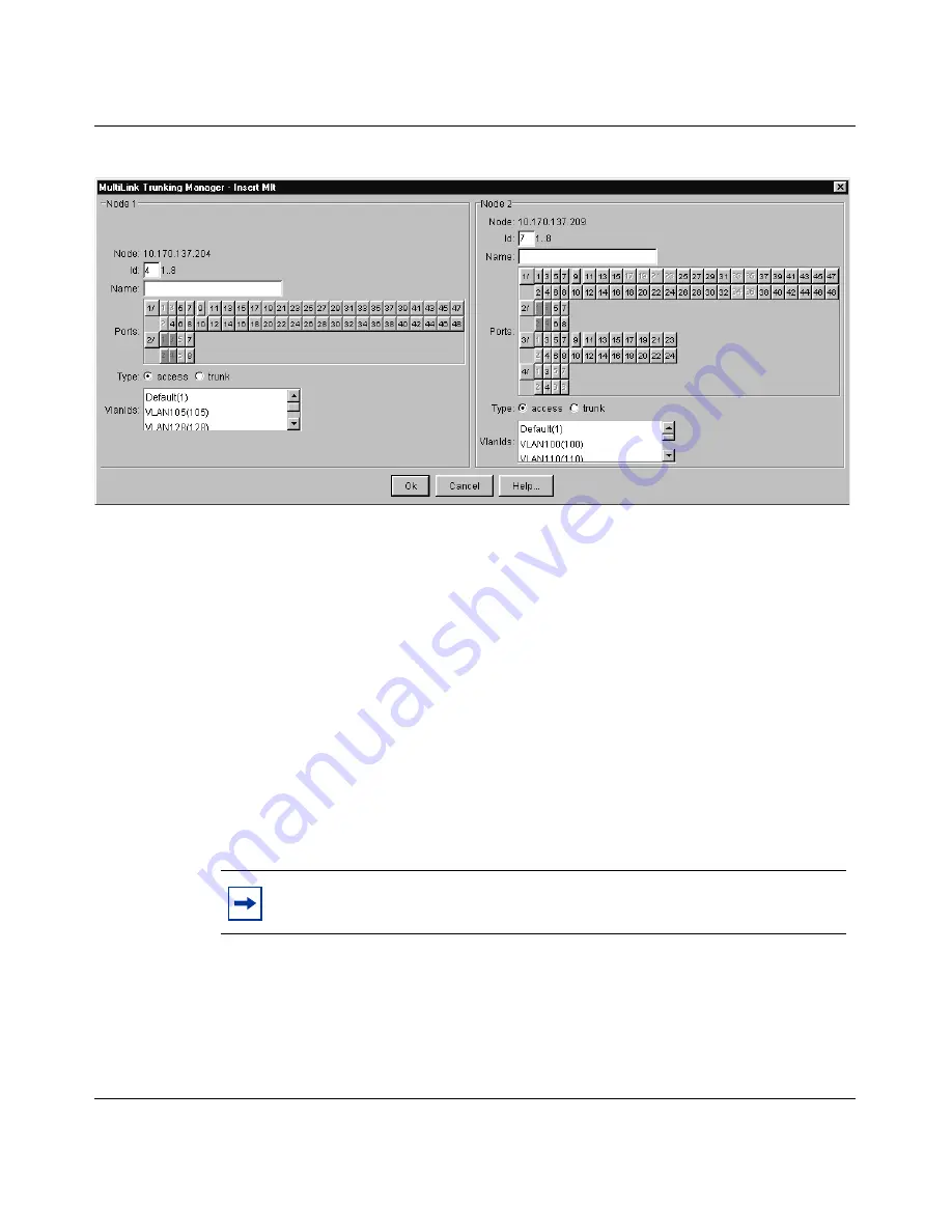
Figure 48
Insert MLT dialog box — pair of devices selected
3
In the Id field for both nodes, select the same Id number for the MLT.
4
In one of the Name fields, type the name of the MLT.
The text you type appears in both Node Name fields.
5
In the Ports text box, select the ports to be added to the MLT.
In the Insert MLT dialog box, port numbers are highlighted in green to
indicate that the ports are already connected between the two devices.
Dimmed port numbers mean that those ports are inactive and cannot be
included in the MLT.
6
Select the MLT type option.
The default is Access.
7
Select the VLAN IDs for both nodes to be included in the MLT port.
8
Click Ok.
Table 35
describes the items in the Insert MLT dialog box for a pair of
devices.
Note:
Both nodes must belong to the same VLAN ID list.
Summary of Contents for Optivity Switch
Page 14: ...14 Figures 208963 B...
Page 22: ...22 Preface 208963 B...
Page 120: ...120 Chapter 5 Using MultiLink Trunking Manager 208963 B...
Page 164: ...164 Chapter 6 Using Multicast Manager 208963 B...
Page 178: ...178 Chapter 7 Using Log Manager 208963 B...
Page 180: ...180 Appendix A Additional reference sources 208963 B...


