background image

INSTALLING AND REMOVING THE OPTIONAL UNIT


5-4


9


Open the front cover and set the 
DIP switches. 

For information on the DIP switch settings, 
refer to step 6 in “3.1 Operation Checks 
During Installation” on page 3-2. 


<Removing components> 

Remove components by following the steps 
for installation in reverse order from step 8. 
 

5.1.2 

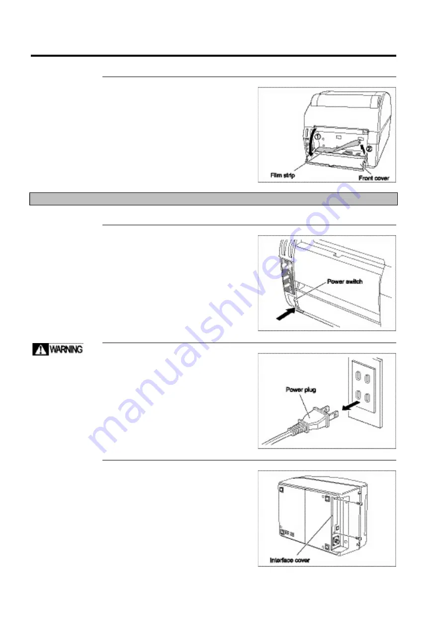
Installing and removing the RS-232C board 

This section explains installation and removal of a RS-232C board. 


1


Press the power switch to turn 
off the printer. 

The POWER light goes off and the power 
shuts off. 


2


Unplug the printer from the 
power outlet. 


3


Turn the printer on its side and 
remove the interface cover by 
removing the two screws. 


Be sure to unplug the 
printer from the 
power outlet. Not 
doing so may result 
in personal injury or 
an equipment 
malfunction. 

Summary of Contents for DURA PRINTER SL

Page 1: ...DURAPRINTER SRs T H E R M A L P R I N T E R I N S T R U C T I O N M A N U A L ...

Page 2: ... proper printing that the operator familiarize himself herself with the commands before transmitting these to the printer The accompanying CD DURA PRINTER SL Setting Tool contains the following Programming the DURA PRINTER SL Setting Tool driver and various instruction manuals For a summary refer to Chapter 6 About the DURA PRINTER SL Setting Tool Copying or reproducing this manual in whole or in ...

Page 3: ...ould be taken closely observing not only the descriptions and explanations in this manual and indications on the body of the product itself but also the safety measures The optional simplified cutter unit contains an assembly with a blade to cut labels Bringing your fingers close to or in contact with this assembly exposes you to a risk of injury or laceration When installing or removing the cutte...

Page 4: ...rranty does not cover malfunctions which result from force majeure or components not supplied by us If the cause of a malfunction cannot be immediately established repair procedures shall be determined upon consultation between the two parties The company shall not be responsible for direct or indirect malfunctions or expenses incurred arising from use of the product supplied We assume no liabilit...

Page 5: ...t symbol Meaning WARNING indicates that a failure to observe instructions may result in death or serious injury to the user CAUTION indicates that a failure to observe instructions may result in minor injury or damage to the device or equipment POINT indicates information which should be observed carefully TIP indicates information which the user will find helpful when operating the printer REFERE...

Page 6: ...cannot be guaranteed If the printer happens to fall it may result in injury Use only AC100V for power Operating the printer at a voltage other than that specified may cause a fire Use only the supplied power cable and AC adapter Be careful not to allow water to come into contact with the main unit and terminals Moisture on or in the equipment may cause a fire or malfunction Do not plug in or unplu...

Page 7: ...r or arm unit Doing so may cause the top cover to come loose and fall resulting in injury or an equipment malfunction Be sure to carry the main unit with the top cover closed Open and close the cover carefully To avoid injury keep your hands away from the area where the cover opens closes Do not allow the top cover to slam shut continue holding the cover until it is fully closed Neglecting to do t...

Page 8: ...assembly may cause a malfunction When transporting the printer first remove the label roll and thermal transfer ribbon Do not locate the printer for extended periods in a location exposed to direct sunlight Doing so may cause a malfunction Do not locate the printer in a location where the temperature and or humidity are high Doing so may cause a malfunction Use only labels and ribbons recommended ...

Page 9: ...ate printing Dust and grit may not only cause a malfunction but also diminish the longevity of the printer When cleaning wipe the printer using a soft cloth dampened with mild detergent and or water Never use thinner or other solvents Doing so may damage the unit or result in a malfunction ...

Page 10: ...vided into sections as follows Procedure layout 1 Describes cautionary remarks notes and reference pages on the left hand side of each page 2 Explains a particular procedure 3 Indicates a particular display or illustration relating to the procedure in question ...

Page 11: ...allation Procedure 1 6 1 3 1 Connecting cables 1 6 1 3 2 Turning on the power 1 7 1 3 3 Turning off the power 1 7 1 4 Installing the Thermal Transfer Ribbon 1 8 1 5 Installing the Label Roll 1 11 1 5 1 Installing the label roll 1 11 1 5 2 Label sensor automatic adjustment 1 14 1 5 3 Installing fan folded paper 1 16 Modifying the top cover 1 16 Installing fan folded paper 1 17 Chapter 2 BASIC OPERA...

Page 12: ...VING THE OPTIONAL UNIT 5 1 5 1 Installing and Removing the Optional Interface 5 2 5 1 1 Installing and removing the LAN board 5 2 5 1 2 Installing and removing the RS 232C board 5 4 5 2 Installing and Removing the Simplified Cutter Unit 5 7 5 3 Installing and Removing the Peeling Unit 5 11 Chapter 6 DURA PRINTER SL SETTING TOOL 6 1 6 1 Launching the DURA PRINTER SL Setting Tool 6 2 6 2 Information...

Page 13: ...PREFACE XII ...

Page 14: ... Consumables Optional Units1 4 1 2 1 Checking the supplied items 1 4 1 2 2 Consumables 1 4 1 2 3 Optional unit 1 5 1 3 Installation Procedure 1 6 1 3 1 Connecting cables 1 6 1 3 2 Turning on the power 1 7 1 3 3 Turning off the power 1 7 1 4 Installing the Thermal Transfer Ribbon 1 8 1 5 Installing the Label Roll 1 11 1 5 1 Installing the label roll 1 11 1 5 2 Label sensor automatic adjustment 1 14...

Page 15: ... and Functions of the Components This section presents the names of various components and explains their functions Read through the following pages to familiarize yourself with the names of the components of the machine Front view ...

Page 16: ...BEFORE OPERATION 1 3 Rear view Operating panel ...

Page 17: ... our company directly To preserve the natural environment biodegradable materials are used for foam cushioning in the package These are environmentally friendly materials Neither black smoke nor toxic gas is produced during disposal via incineration 1 2 2 Consumables Make sure to use labels and ribbons recommended by NITTO DENKO corporation The thermal head platen roller and label guide are consum...

Page 18: ...ional units are available for this unit When you purchase an optional unit check that all appropriate items are in the package The equipment does not have a print server function Therefore it is not possible to simultaneously print data from multiple computers ...

Page 19: ...ng it clockwise 3 Connect the USB cable to the printer Insert the accompanying USB cable into the USB port If an optional board LAN interface or RS 232C interface has been installed also connect the corresponding cable 4 Connect the cable to the computer 5 Insert the power plug into the outlet Do not plug several power cables into the same outlet by means of an adapter for example An overload may ...

Page 20: ...rinter The POWER light comes on The ONLINE light comes on after a few seconds the printer is now online 1 3 3 Turning off the power 1 Press the power switch to turn off the printer The POWER light goes off and the power shuts off Check that printing is complete before turning off the power ...

Page 21: ...lever toward you and then raise the arm unit 4 Insert the ribbon spindle into the ribbon take up area Pull and hold the ribbon holder and put the ribbon spindle in position Then release the holder When replacing the ribbon remove the old ribbon spindle from the ribbon supply area and insert it in the take up area Open the top cover gently Opening the cover abruptly or extending it beyond 90 degree...

Page 22: ...le should match the width of the ribbon 7 Rotate the ribbon spindle clockwise winding the ribbon until the carbon side comes to the front 8 Lock the arm unit Lower the arm unit Then press where it says PUSH on either side to lock the arm unit If the arm unit does not lock the first time press PUSH again to lock it Pass the ribbon between the label retaining roller and the thermal head Wind the rib...

Page 23: ...BEFORE OPERATION 1 10 9 Close the top cover 10 Press the power switch to turn on the printer The POWER and ONLINE lights come on the printer is now online ...

Page 24: ...elease them Then slide the tabs to the correct position depending on the label width Refer to the scale to find the correct position 5 Check the platen roller For backing paper less than 63 mm wide use a narrow platen roller To replace the platen roller refer to Section 4 3 Replacing the Platen Roller Open the top cover gently Opening the cover abruptly or extending it beyond 90 degrees to the pla...

Page 25: ...lders are not close enough to the roll squeeze the label holder tabs bringing the holders closer to the roll and eliminating the gap Now check that the labels advance smoothly and in a straight path If any holder pin is protruding toward the inside the label roll cannot be held in position Before positioning the roll lift the holder pin and tilt it outwards If the gap between the label holder and ...

Page 26: ...ard configuration unit or is equipped with the simplified cutter unit skip this step Open the front cover and unfold the peeling arm Pass the backing paper under the front cover and reposition the peeling arm as it was Gently pull the backing paper so that it is taut 11 Close the top cover 12 Press the power switch to turn on the printer The POWER and ONLINE lights come on the printer is now onlin...

Page 27: ...ally adjust its own label sensor sensitivity This adjustment is carried out when a label roll with a different type of backing paper is used the print position is not adjusted correctly or a label size error occurs repeatedly It is also possible to adjust the label sensor automatically via the Setup Utility 1 Set the label roll so that a label is positioned under the label sensor 2 Check that the ...

Page 28: ...le pressing the ONLINE button press the FEED button and release fingers at the same time A buzzer sounds twice after the button is pressed 5 Press the ONLINE button 0 appears in the 7 segment LED of the error display area 6 Press the FEED button to advance the label roll by a few labels Verify that the roll stops at each label position To start printing press the ONLINE button to make the printer ...

Page 29: ...difying the top cover 1 Press the power switch to turn off the printer The POWER light goes off and the power shuts off 2 Open and remove the top cover Press the left and right triangle marks on the top cover to unlock the cover Gently opening the cover beyond 90 degrees to the plane of the printer itself as shown in the illustration releases the top cover at hinged contact points Open the top cov...

Page 30: ...lling fan folded paper 1 Press the power switch to turn off the printer The POWER light goes off and the power shuts off 2 Open the top cover Press the left and right triangle marks on the top cover to unlock and open the cover Open the top cover gently Opening the cover abruptly or extending it beyond 90 degrees to the plane of the printer itself may cause the cover to come loose and fall Be sure...

Page 31: ...hat the labels will advance straight through the printer during printing 5 Adjust the label holders to match the width of the label roll Squeeze the label holder tabs to release them Then slide the tabs to the correct position depending on the label width Refer to the scale to find the correct position If the gap between the label holder and the label roll is too large the labels may drift resulti...

Page 32: ...e not close enough to the fan folded paper squeeze the label holder tabs to release them and slide the holders closer to the paper to eliminate the gap Now check that the labels advance smoothly and in a straight path 8 Lock the arm unit Lower the arm unit Then press where it says PUSH on either side to lock the arm unit If the arm unit does not lock the first time press PUSH again to lock it If t...

Page 33: ...reposition the peeling arm as it was Gently pull the backing paper so that it is taut 10 Close the top cover 11 Press the power switch to turn on the printer The POWER and ONLINE lights come on the printer is now online 12 The uptake point of the label roll is located Press the ONLINE button to make the printer go offline Then press the FEED button several times Check that the labels advance smoot...

Page 34: ...y to operate the printer 2 1 Before Starting Work 2 2 2 1 1 Checks before operation 2 2 2 2 Online and Offline 2 3 2 2 1 Operating in online mode 2 4 Switching to online mode 2 4 2 2 2 Operating in offline mode 2 5 Switching to offline mode 2 5 Locating the uptake point of the label roll 2 6 ...

Page 35: ... dust or grime After removing any residual dust or grime which may have accumulated from the labels passing through the printer wipe the thermal head using a cotton swab dipped in cleaning solution For further information refer to Cleaning the Thermal Head and Platen Roller on page 4 2 Check the platen roller for dust or grime After removing dust or label grime wipe the platen roller using a cloth...

Page 36: ...rinter and be printed On the other hand if the printer is offline it is effectively disconnected from the computer and consequently data cannot be transmitted or printed If for whatever reason troubleshooting is necessary or when a few labels must be fed into the printer before printing ensure that the printer is offline ...

Page 37: ... is in process Online mode To enter online mode proceed as follows Switching to online mode 1 Press the ONLINE button The ONLINE light comes on If print data still remains in the printer s memory printing resumes If an error occurs the ERROR light illuminates and a number other than 0 appears in the error display area The printer can return to online mode only after the error has been cancelled an...

Page 38: ... has been interrupted printing resumes Press the FEED button to feed the labels so that the uptake point of the label roll comes front Offline mode To make the printer go offline proceed as follows Switching to offline mode 1 Press the ONLINE button The ONLINE light goes off signifying that the printer is now in offline mode If print data still remains in the printer s memory printing stops ...

Page 39: ...printing is interrupted or when labels run out and need to be replaced follow the procedure below to resume printing 1 Press the FEED button several times Labels advance as necessary to determine the label start point The FEED button only operates when the printer is offline ...

Page 40: ...SETUP PROCEDURE 3 1 SETUP PROCEDURE This chapter explains how to set up the printer 3 1 Operation Checks During Installation 3 2 ...

Page 41: ... desktop if this shortcut icon is available If the DURA PRINTER SL Setting Tool has not yet been installed Start the computer and insert the accompanying disk containing the DURA PRINTER SL Setting Tool into the CD drive The DURA PRINTER SL Setting Tool launches and the menu screen appears 3 Open the front cover 4 Lift the right end of the film strip Be sure to turn off the power Not doing so may ...

Page 42: ...label depending on the amount of light transmitted 4 This specifies either thermal transfer mode or direct thermal mode ON ON Specifies thermal transfer mode OFF Specifies direct thermal mode 5 This allows detection of broken pins on the thermal head ON ON Detects broken pins OFF Does not detect broken pins In this case if there are in fact broken pins on the head no error appears in the 7 segment...

Page 43: ... 4 6 After the DIP switches have been set replace the film strip and front cover in their original positions 7 Press the power switch to turn on the printer The POWER and ONLINE lights come on the printer is now online ...

Page 44: ...ing the Thermal Head and Platen Roller 4 2 4 2 Replacing the Thermal Head 4 6 4 3 Replacing the Platen Roller 4 10 4 4 Replacing the Label Guide 4 13 4 5 Cleaning the Optional Unit 4 16 4 5 1 Peeling unit 4 16 4 5 2 Simplified cutter unit 4 19 4 6 Checking the Label Sensor 4 22 4 7 Checking the Peeling Sensor 4 23 ...

Page 45: ...ight goes off and the power shuts off 2 Open the top cover Press the left and right triangle marks on the top cover to unlock and open the cover 3 Pull the print head locking lever toward you and then raise the arm unit 4 Remove the thermal transfer ribbon Be sure to turn off the power Not doing so may result in personal injury or an equipment malfunction Open the top cover slowly Opening the cove...

Page 46: ...e cotton swab which let isopropyl alcohol soak 7 While rotating the platen roller wipe it with the cloth which let isopropyl alcohol soak Cleaning solution is inflammable After use close the cap securely to avoid the possibility of fire Do not touch the thermal head with bare hands This may cause a printing failure ...

Page 47: ...on either side to lock the arm unit If the arm unit does not lock the first time press PUSH again to lock it 10 Close the top cover For information on how to install the thermal transfer ribbon refer to Installing the Thermal Transfer Ribbon on page 1 8 and for information on how to install the label roll refer to Installing the Label Roll on page 1 11 ...

Page 48: ...MAINTENANCE 4 5 11 Press the power switch to turn on the printer The POWER and ONLINE lights come on the printer is now online ...

Page 49: ... and right triangle marks on the top cover to unlock and open the cover 3 Pull the print head locking lever toward you and then raise the arm unit 4 Remove the thermal transfer ribbon Be sure to turn off the power Not doing so may result in personal injury or an equipment malfunction Open the top cover gently Opening the cover abruptly or extending it beyond 90 degrees to the plane of the printer ...

Page 50: ...hown while supporting the thermal head with your hand After inserting the hooks move the thermal head retaining lever back in position Do not exert excessive force on the connectors harnesses or cables Return the connectors harnesses to their original positions ensuring that they do not make contact with the thermal transfer ribbon Do not touch the thermal head with bare hands This may cause a pri...

Page 51: ... Install the thermal transfer ribbon 11 Lock the arm unit Lower the arm unit Then press where it says PUSH on either side to lock the arm unit If the arm unit does not lock the first time press PUSH again to lock it 12 Close the top cover For information on how to install the thermal transfer ribbon refer to Installing the Thermal Transfer Ribbon on page 1 8 ...

Page 52: ...MAINTENANCE 4 9 13 Press the power switch to turn on the printer The POWER and ONLINE lights come on the printer is now online ...

Page 53: ...ight triangle marks on the top cover to unlock and open the cover Then pull the upper part of the front cover toward you to open the cover 4 Pull the print head locking lever toward you and then raise the arm unit Open the top and front covers gently Opening the cover abruptly or extending it beyond 90 degrees to the plane of the printer itself may cause the cover to come loose and fall Be sure to...

Page 54: ...e label guide backwards Then lift the guide to remove it 7 Change the platen roller Move the platen roller to the right and pull it upward when the metal bushing is released 8 Install the label guide Insert the mounting tab on either side of the label guide into the notch and then tilt the guide toward you Be careful not to catch your fingers in the unit ...

Page 55: ...int head locking lever 10 Lock the arm unit Lower the arm unit Then press where it says PUSH on either side to lock the arm unit If the arm unit does not lock the first time press PUSH again to lock it 11 Close the top and front covers ...

Page 56: ...ht triangle marks on the top cover to unlock and open the cover Then pull the upper part of the front cover toward you to open the cover 4 Pull the print head locking lever toward you and then raise the arm unit Open the top and front covers gently Opening the cover abruptly or extending it beyond 90 degrees to the plane of the printer itself may cause the cover to come loose and fall Be sure to u...

Page 57: ...ver 6 Remove the label guide Tilt the front of the label guide backwards Then lift the guide to remove it 7 Install the new label guide Insert the mounting tab on either side of the label guide into the notch and then tilt the guide toward you 8 Replace the print head locking lever 誤って指などをはさま ないように注意してくだ さい ...

Page 58: ... 15 9 Lock the arm unit Lower the arm unit Then press where it says PUSH on either side to lock the arm unit If the arm unit does not lock the first time press PUSH again to lock it 10 Close the top and front covers ...

Page 59: ...f 2 Open the top and front covers Press the left and right triangle marks on the top cover to unlock and open the cover Then pull the upper part of the front cover toward you to open the cover 3 Pull the print head locking lever toward you and then raise the arm unit 4 After winding any unwound labels back onto the roll remove the roll Be sure to turn off the power Not doing so may result in perso...

Page 60: ...ing replace the label roll reposition the peeling arm and close the front cover 8 Lock the arm unit Lower the arm unit Then press where it says PUSH on either side to lock the arm unit If the arm unit does not lock the first time press PUSH again to lock it For information on how to install the label roll refer to Installing the Label Roll on page 1 11 Cleaning solution is inflammable After use cl...

Page 61: ...MAINTENANCE 4 18 9 Close the top cover 10 Press the power switch to turn on the printer The POWER and ONLINE lights come on the printer is now online ...

Page 62: ... the cover Then pull the upper part of the front cover toward you to open the cover 3 Pull the print head locking lever toward you and then raise the arm unit 4 After winding any unwound labels back onto the roll remove the roll Be sure to turn off the power Not doing so may result in personal injury or an equipment malfunction Open the top and front covers gently Opening the cover abruptly or ext...

Page 63: ...he cutter so that the labels advance easily 8 After cleaning close the front cover and replace the label roll For information on how to install the label roll refer to Installing the Label Roll on page 1 11 Be careful not to touch the blade of the simplified cutter unit Be sure to rotate the shaft gear clockwise Rotating it counterclockwise may damage the simplified cutter unit Be sure to rotate t...

Page 64: ...ess where it says PUSH on either side to lock the arm unit If the arm unit does not lock the first time press PUSH again to lock it 10 Close the top cover 11 Press the power switch to turn on the printer The POWER and ONLINE lights come on the printer is now online ...

Page 65: ...D button H appears on the 7 segment LED in the error display area 3 Place a label in the label sensor area Align the white area of the label with the sensor area 4 Press the FEED button After pressing the button wait until the buzzer sounds 5 Press the ONLINE button 0 appears on the 7 segment LED in the error display area 4 Press the FEED button to advance the roll by three labels or so Check whet...

Page 66: ...r is offline the ONLINE light is off When the printer is online press the ONLINE button to make it go offline 2 Check the position of the peeling sensor Check the position of the sensor by checking the 7 segment LED in the error display area When is displayed on the LED this means that a label is present When 0 is displayed on the LED this means that no label is present ...

Page 67: ...MAINTENANCE 4 24 ...

Page 68: ...mation on how to install and remove the optional unit 5 1 Installing and Removing the Optional Interface 5 2 5 1 1 Installing and removing the LAN board 5 2 5 1 2 Installing and removing the RS 232C board 5 4 5 2 Installing and Removing the Simplified Cutter Unit 5 7 5 3 Installing and Removing the Peeling Unit 5 11 ...

Page 69: ... explains installation and removal of the LAN board 1 Press the power switch to turn off the printer The POWER light goes off and the power shuts off 2 Unplug the printer from the power outlet 3 Turn the printer on its side and remove the interface cover by removing two screws 4 Now remove the two screws which hold the bottom cover in place remove the cover Be sure to unplug the printer from the p...

Page 70: ... the way home into the receiving connector and aligning the two spacers 6 Secure the LAN board in position with the two screws supplied 7 Secure the LAN cover with the two screws 8 Replace the bottom cover securing it with the two screws removed earlier Now put the printer back in its normal position on a level surface ...

Page 71: ...reverse order from step 8 5 1 2 Installing and removing the RS 232C board This section explains installation and removal of a RS 232C board 1 Press the power switch to turn off the printer The POWER light goes off and the power shuts off 2 Unplug the printer from the power outlet 3 Turn the printer on its side and remove the interface cover by removing the two screws Be sure to unplug the printer ...

Page 72: ...the bottom cover 5 Mount the interface board on the main board pushing the board s connector all the way home into the receiving connector and aligning the two spacers 6 Secure the interface board in position with the two screws supplied 7 Secure the board cover with the two screws ...

Page 73: ... the printer back in its normal position on a level surface 9 Open the front cover and set the DIP switches For information on the DIP switch settings refer to step 6 in 3 1 Operation Checks During Installation on page 3 2 Removing components Remove components by following the steps for installation in reverse order from step 8 ...

Page 74: ...over Gently opening the cover beyond 90 degrees to the plane of the printer itself as shown in the illustration releases the top cover at hinged contact points Then pull the upper part of the front cover toward you to open the cover 4 Remove the plastic part from the rear of the top cover Cut five notches in the plastic part on the rear of the top cover using a cutting pliers Be sure to unplug the...

Page 75: ...in their corresponding slots on the printer to secure the cover 6 Pull the print head locking lever toward you and then raise the arm unit 7 Raise the right end of the film strip 8 Gently remove a notch from the film strip for the optional unit connector The left end of the film strip is secured by the tape The strip may become distorted if it is bent excessively ...

Page 76: ... to the groove 11 Connect the simplified cutter unit s connector to the printer 12 Install the simplified cutter unit on the printer inserting the hooks into the two slots and pushing the unit downward as shown in the illustration Install the simplified cutter unit so that there is no gap between the left and right stoppers on the simplified cutter unit and the label guide Be careful not to touch ...

Page 77: ... the arm unit Lower the arm unit Then press where it says PUSH on either side to lock the arm unit If the arm unit does not lock the first time press PUSH again to lock it 15 Close the front and top covers Removing components Remove components by following the steps for installation in reverse order from step 15 ...

Page 78: ... Press the left and right triangle marks on the top cover to unlock and open the cover Then pull the upper part of the front cover toward you to open the cover 4 Pull the print head locking lever toward you and then raise the arm unit Be sure to unplug the printer from the power outlet Not doing so may result in personal injury or an equipment malfunction Open the top and front covers gently Openi...

Page 79: ...he DIP switch settings of the printer Change the settings as they apply to peeling mode referring to step 6 in 3 1 Operation Checks During Installation on page 3 2 8 Replace the film strip in its original position Position the film strip aligning it to the groove The left end of the film strip is secured by the tape The strip may become distorted if it is bent excessively ...

Page 80: ...m 11 Install the peeling unit on the printer inserting the hooks into the two slots and pushing the unit downward as shown in the illustration 12 After the peeling unit has been secured with the two screws reposition the peeling arm Then push the arm into the unit to lock it Be careful neither to compress the cable of the peeling unit nor to position the peeling unit in the front of the main unit ...

Page 81: ...lt the front of the label guide For standard unit backwards Then lift the guide to remove it 15 Install the label guide supplied with the peeling unit For the peeling unit Insert the mounting tab on either side of the label guide For the peeling unit into the notch and then tilt the guide toward you 16 Replace the print head locking lever Be careful not to catch your fingers in the unit ...

Page 82: ...in to lock it 18 Close the front cover and apply the non adhesive tape to the upper part of the cover Then close the top cover Removing components Remove components by following the steps for installation in reverse order from step 18 If the square notch of the front cover is incorrectly aligned with the notch in the non adhesive tape the peeling sensor may malfunction Make sure that these are ali...

Page 83: ...INSTALLING AND REMOVING THE OPTIONAL UNIT 5 16 ...

Page 84: ...iew of the DURA PRINTER SL Setting Tool and explains how it is launched 6 1 Launching the DURA PRINTER SL Setting Tool 6 2 6 2 Information on the DURA PRINTER SL Setting Tool 6 3 6 2 1 DURA PRINTER SL Setting Tool menu screen 6 3 6 2 2 Manuals menu screen 6 4 6 2 3 Installation menu screen 6 5 ...

Page 85: ... Tool This chapter explains how to launch the DURA PRINTER SL Setting Tool 1 Start the computer 2 Insert the accompanying disk containing the DURA PRINTER SL Setting Tool into the CD drive After a few moments the DURA PRINTER SL Setting Tool starts and the menu screen appears ...

Page 86: ...ng instructions for the DURA PRINTER SL and various explanations and instructions for other software that accompanies the DURA PRINTER SL Setting Tool Refer to 6 2 2 Manuals menu on page 6 4 for further details of this screen When this button is clicked or the F4 key on the keyboard is pushed the printer selection screen appears This allows settings of the DURA PRINTER SL connected to the computer...

Page 87: ...Manual in PDF format opens This manual describes commands used in the DURA PRINTER SL When this button is clicked or the F4 key on the keyboard is pushed the Interface Instruction Manual in the PDF format opens This manual describes the DURA PRINTER SL interfaces When this button is clicked or the F5 key on the keyboard is pressed the Printer Driver Instruction Manual in PDF format opens This manu...

Page 88: ... the keyboard is pressed the printer driver installation screen appears Refer to the DURA PRINTER SL Setting Tool manual on the accompanying CD ROM for details on how to proceed after clicking this button When this button is clicked or the F4 key on the keyboard is pressed the DURA PRINTER SL Setting Tool installation screen appears Refer to the manual on the accompanying CD ROM for details on how...

Page 89: ...DURA PRINTER SL SETTING TOOL 6 6 ...

Page 90: ...hapter explains troubleshooting in the event of an error message or other problem The chapter also contains the index and specifications lists 7 1 Troubleshooting 7 2 7 2 Specifications 7 4 7 3 Label Restrictions 7 5 7 4 Index 7 6 ...

Page 91: ...ptake point of the label roll When the uptake point is correctly located press the ONLINE button If the uptake point is not correctly located have the label sensor adjust itself automatically If non standard labels are to be used it is necessary to adjust the sensor separately Contact your dealer in this case Out of ribbon The ribbon has run out during thermal transfer printing After loading a rib...

Page 92: ...labels Wait until the temperature of the thermal head drops below 60 C Printing will then resume automatically Buffer overload The number of commands transmitted to the printer exceeds memory capacity or the computer does not control the communication correctly Turn off the power and specify the correct printing command via the computer s application Then restart printing Thermal head not yet inst...

Page 93: ... Kanji character 16 16 dots JIS levels I and II Gothic letters 24 24 dots JIS levels I and II Gothic letters Outline font Gothic letters alphanumeric symbol katakana phonetic script OCR B 40 48 dots Character magnification When an exclusive command is used 1 to 12 times It is possible to specify both height and width of a character using individual magnifications Barcode When an exclusive command ...

Page 94: ...re printed Ruled lines are defined as lines between 4 dots 0 25 mm and 10 dots 0 625 mm in width In cases where the label pitch has a value obtained by the following equation label error or skips may occur N P 1 56 mm N 1 to7 Please select a label pitch not within this range N NG pitch P mm 1 55 to 57 2 27 5 to 28 5 3 18 3 to 19 4 13 7 to 14 3 5 11 to 11 4 6 9 1 to 9 5 7 7 8 to 8 2 ...

Page 95: ... Installing the label roll 1 11 Installing the LAN board 5 2 Installing the optional interface 5 2 Installing the peeling unit 5 11 Installing the RS 232C board 5 4 Installing the simplified cutter unit 5 7 Installing the thermal transfer ribbon 1 8 L Label guide 1 2 Label holder tab 1 2 Label holders 1 2 Label retaining roller 1 2 Label restrictions 7 5 Labels 1 4 LAN connector 1 3 LAN interface ...

Page 96: ...r 4 10 Replacing the thermal head 4 6 Ribbon holders 1 2 Ribbon spindle 1 4 Ribbon supply area 1 2 Ribbon take up area 1 2 RS 232C interface 1 5 RS 232C port 1 3 S Simplified cutter unit 1 2 Specifications 7 4 Supplied items 1 4 T Thermal head 1 2 Thermal head cleaner 1 4 Thermal transfer ribbon 1 4 Top cover 1 2 Transmission sensor 1 2 Troubleshooting 7 2 Turning off the power 1 7 Turning on the ...

Page 97: ...APPENDIX 7 8 ...

Page 98: ...P N A2136E ...

Reviews: